SiUS371901E
225
Service Diagnosis
Part 6
Service Diagnosis
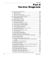
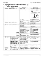
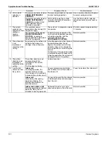
1. Symptom-based Troubleshooting ........................................................... 228
Gas Furnace Lockout Reset..................................................................... 231
With Optional Infrared Presence/Floor Sensor......................................... 232
2. Troubleshooting with Remote Controller ................................................. 233
Wireless Remote Controller ..................................................................... 234
3. Troubleshooting by Error Code ............................................................... 236
Error Codes and Descriptions .................................................................. 236
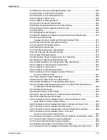
External Protection Device Abnormality ................................................... 251
Indoor Unit Control PCB Abnormality ....................................................... 253
Drain Level Control System Abnormality.................................................. 254
Indoor Fan Motor Lock, Overload............................................................. 256
Indoor Fan Motor Abnormality .................................................................. 258
Overload/Overcurrent/Lock of Indoor Fan Motor...................................... 262
Blower Motor Not Running ....................................................................... 263
3.10 Indoor Fan Motor Status Abnormality....................................................... 264
3.11 Low Indoor Airflow.................................................................................... 265
3.12 Swing Flap Motor Abnormality ................................................................. 266
3.13 Power Supply Voltage Abnormality .......................................................... 268
3.14 Blower Motor Stops for Over/Under Voltage ............................................ 269
3.15 Electronic Expansion Valve Coil Abnormality, Dust Clogging .................. 270
3.16 Gas Furnace Abnormality......................................................................... 271
3.17 Drain Level above Limit ............................................................................ 272
3.18 Capacity Determination Device Abnormality ............................................ 273
3.19 Transmission Abnormality between Indoor Unit Control PCB and
3.20 Blower Motor Communication Error ......................................................... 276
3.21 Climate Talk Communication Error .......................................................... 277
3.22 Thermistor Abnormality ............................................................................ 278
3.23 Combination Error between Indoor Unit Control PCB and Fan PCB ....... 279
3.24 Blower Motor HP Mismatch...................................................................... 280
3.25 Indoor Blower Does Not Have Required Parameters to Function ............ 281
3.26 Remote Sensor Abnormality .................................................................... 282
3.27 Humidity Sensor System Abnormality ...................................................... 283
3.28 Infrared Presence/Floor Sensor Error ...................................................... 284
3.29 Remote Controller Thermistor Abnormality .............................................. 289
3.30 Outdoor Unit Main PCB Abnormality ........................................................ 290
3.31 Detection of Ground Leakage by Leak Detection Circuit ......................... 291
Summary of Contents for REYQ72-456XATJU
Page 415: ...SiUS371901E Wiring Diagrams Appendix 402 REYQ144 168XATJU 2D119206A ...
Page 416: ...Wiring Diagrams SiUS371901E 403 Appendix REYQ72 96 120XAYDU 2D119207B ...
Page 417: ...SiUS371901E Wiring Diagrams Appendix 404 REYQ144 168XAYDU 2D119208B ...
Page 418: ...Wiring Diagrams SiUS371901E 405 Appendix REYQ72 96 120 144 168XAYCU 2D119209A ...
Page 421: ...SiUS371901E Wiring Diagrams Appendix 408 FXZQ05 07 09 12 15 18TAVJU 3D110443A ...
Page 423: ...SiUS371901E Wiring Diagrams Appendix 410 FXEQ07 09 12 15 18 24PVJU 3D098557A ...
Page 426: ...Wiring Diagrams SiUS371901E 413 Appendix FXMQ07 09 12 15 18 24 30 36 48 54PBVJU 3D093209B ...
Page 428: ...Wiring Diagrams SiUS371901E 415 Appendix FXHQ12 24 36MVJU 3D048116C ...
Page 429: ...SiUS371901E Wiring Diagrams Appendix 416 FXAQ07 09 12 18 24PVJU C 3D075354D ...
Page 435: ...SiUS371901E Wiring Diagrams Appendix 422 VAM1200GVJU 3D073270D ...
Page 437: ...SiUS371901E Wiring Diagrams Appendix 424 1 4 2 Multi Branch Selector Unit BS4Q54TVJ 3D089123B ...
Page 438: ...Wiring Diagrams SiUS371901E 425 Appendix BS6 8Q54TVJ 2D089122B ...
Page 439: ...SiUS371901E Wiring Diagrams Appendix 426 BS10 12Q54TVJ 2D089121B ...
Page 440: ...Revision History Month Year Version Revised contents 04 2019 SiUS371901E First edition ...


