SiUS371901E
Troubleshooting by Error Code
Service Diagnosis
266
3.12 Swing Flap Motor Abnormality
Error Code
A7
Applicable
Models
FXHQ-M, FXAQ-P
Method of Error
Detection
Utilizes ON/OFF of the limit switch when the motor turns.
Error Decision
Conditions
When ON/OFF of the micro-switch for positioning cannot be reversed even though the swing flap
motor is energized for a specified amount of time (about 30 seconds).
∗
Error code is displayed but the system operates continuously.
Supposed
Causes
Defective swing motor
Defective connection cable (power supply and limit switch)
Defective airflow direction adjusting flap-cam
Defective indoor unit control PCB
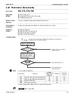
Troubleshooting
Indoor unit is
a model equipped with a
swing flap function
The swing
motor works when
the power supply is turned OFF
and then restart.
The relay
cable is short circuited
or disconnected.
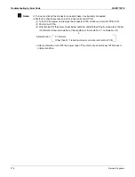
Caution
Be sure to turn off the power switch before connecting or disconnecting
connectors, or parts may be damaged.
Provide 208-230 V power
supply.
YES
NO
The
connector is
connected to the indoor
unit control PCB.
(
∗
1)
Go to the next page.
Replace the limit switch
relay cable.
Replace the indoor unit control
PCB (A1P).
NO
YES
YES
NO
YES
Connect the connector (
∗
1)
and turn the power supply on
again.
Replace the indoor unit control
PCB (A1P).
NO
NO
YES
NO
YES
YES
NO
Replace the defective
swing motor. (
∗
2)
Is power supply 208-
230 V provided?
The limit switch
functions normally.
After
turning
the swing-flap
ON and then
stopping with the
remote controller, the
voltage of the connector
(
∗
1) is 208-230 VAC
when turned ON
again (within 30
seconds of
turning ON
again).
A
Summary of Contents for REYQ72-456XATJU
Page 415: ...SiUS371901E Wiring Diagrams Appendix 402 REYQ144 168XATJU 2D119206A ...
Page 416: ...Wiring Diagrams SiUS371901E 403 Appendix REYQ72 96 120XAYDU 2D119207B ...
Page 417: ...SiUS371901E Wiring Diagrams Appendix 404 REYQ144 168XAYDU 2D119208B ...
Page 418: ...Wiring Diagrams SiUS371901E 405 Appendix REYQ72 96 120 144 168XAYCU 2D119209A ...
Page 421: ...SiUS371901E Wiring Diagrams Appendix 408 FXZQ05 07 09 12 15 18TAVJU 3D110443A ...
Page 423: ...SiUS371901E Wiring Diagrams Appendix 410 FXEQ07 09 12 15 18 24PVJU 3D098557A ...
Page 426: ...Wiring Diagrams SiUS371901E 413 Appendix FXMQ07 09 12 15 18 24 30 36 48 54PBVJU 3D093209B ...
Page 428: ...Wiring Diagrams SiUS371901E 415 Appendix FXHQ12 24 36MVJU 3D048116C ...
Page 429: ...SiUS371901E Wiring Diagrams Appendix 416 FXAQ07 09 12 18 24PVJU C 3D075354D ...
Page 435: ...SiUS371901E Wiring Diagrams Appendix 422 VAM1200GVJU 3D073270D ...
Page 437: ...SiUS371901E Wiring Diagrams Appendix 424 1 4 2 Multi Branch Selector Unit BS4Q54TVJ 3D089123B ...
Page 438: ...Wiring Diagrams SiUS371901E 425 Appendix BS6 8Q54TVJ 2D089122B ...
Page 439: ...SiUS371901E Wiring Diagrams Appendix 426 BS10 12Q54TVJ 2D089121B ...
Page 440: ...Revision History Month Year Version Revised contents 04 2019 SiUS371901E First edition ...


