SiUS371901E
Check
Service Diagnosis
374
4. Check
4.1
High Pressure Check
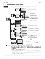
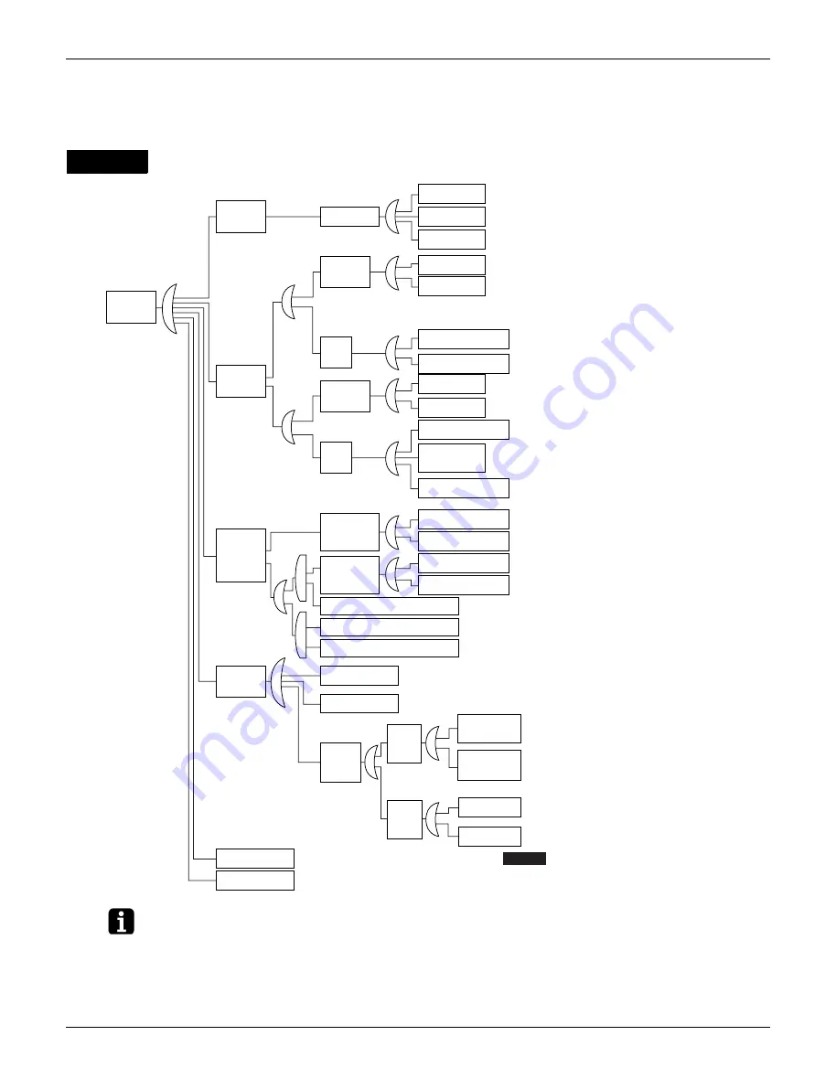
Referring to the Fault Tree Analysis (FTA) shown below, probe the defective points.
Notes:
∗
1. In cooling, it is normal if the outdoor unit electronic expansion valve (main) is fully open.
∗
2. In heating, the indoor unit electronic expansion valve is used for subcooling degree control.
CHECK 1
Short circuit
Rise in high
pressure
Local
pressure
rise
High pipe
resistance
Stop valve closed
Bent or crashed pipe
Clogging of foreign
materials
[In cooling]
If the outdoor unit electronic
expansion valve is throttled:
(
∗
1.)
Defective outdoor
unit electronic
expansion valve
Defective indoor
unit electronic
expansion valve
Defective valve coil
Defective valve body
A temperature difference
in excess of 10
°
C (18
°
F) between
the inlet and the outlet is deemed
to be abnormal.
Defective
control
Defective high pressure sensor
Defective outdoor
unit main PCB
Defective
high pressure
control
Defective valve coil
Defective valve body
[In heating]
If the indoor unit electronic
expansion valve excessively
throttled:
(
∗
2.)
Defective
control
Defective high pressure sensor
Defective indoor unit
liquid pipe thermistor
[In cooling]
High suction
air
temperature
of the
condenser
[In heating]
High suction air
temperature of
outdoor unit
Short circuit
High outdoor air
temperature
High suction
air temperature
of indoor unit
High room
temperature
Defective suction air thermistor of indoor unit
High suction air temperature of outdoor unit
Defective outdoor air temperature thermistor of outdoor unit
Degradation
in condensing
capacity
Dirty condenser
Mixing of non-condensable gas
Decreased
airflow rate
Decreased
fan
output
Defective fan
motor
Defective outdoor unit
main PCB (Including
capacity setting)
High
airflow
passage
resistance
Dirty filter
Obstacle
Excessive refrigerant charging
Improper model selection [In heating]
←
Check to be sure the stop valve is open.
←
Conduct visual checks for pipe conditions.
←
Is there any temperature difference caused before
and after the filter or branch pipe?
←
Are the coil resistance and insulation normal?
←
Is the pressure value checked with the Service Checker
corresponding to the measurement value of the pressure sensor?
←
Are the voltage characteristics normal?
←
Are the coil resistance and insulation
normal?
←
Is the pressure value checked with the Service
Checker corresponding to the measurement value of
the pressure sensor?
←
Is the connector properly connected?
Are the thermistor resistance characteristics normal?
←
Are the voltage characteristics normal?
←
Is the suction air temperature less than 43
°
C (109.4
°
F)?
←
Is the outdoor air temperature less than 43
°
C (109.4
°
F)?
←
Is the suction air temperature less than 27
°
C (80.6
°
F)?
←
Is the room temperature less than 27
°
C (80.6
°
F)?
←
Is the connector properly connected?
Are the thermistor resistance characteristics normal?
←
Is the outdoor air temperature less than 16
°
CWB?
←
Is the connector properly connected?
Are the thermistor resistance characteristics normal?
←
Is the heat exchanger clogged? (In cooling)
←
Is air or else mixed in the refrigerant system?
←
Can the fan motor be rotated with hands?
Are the motor coil resistance and
insulation normal?
←
If a spare PCB is mounted, is the capacity
setting properly made?
←
Is the air filter clogged?
←
Is there any obstacle in the airflow passage?
←
Refer to
CHECK 6
.
←
Is the indoor unit too small compared to
the large-sized outdoor unit?
Defective outdoor
unit main PCB
Summary of Contents for REYQ72-456XATJU
Page 415: ...SiUS371901E Wiring Diagrams Appendix 402 REYQ144 168XATJU 2D119206A ...
Page 416: ...Wiring Diagrams SiUS371901E 403 Appendix REYQ72 96 120XAYDU 2D119207B ...
Page 417: ...SiUS371901E Wiring Diagrams Appendix 404 REYQ144 168XAYDU 2D119208B ...
Page 418: ...Wiring Diagrams SiUS371901E 405 Appendix REYQ72 96 120 144 168XAYCU 2D119209A ...
Page 421: ...SiUS371901E Wiring Diagrams Appendix 408 FXZQ05 07 09 12 15 18TAVJU 3D110443A ...
Page 423: ...SiUS371901E Wiring Diagrams Appendix 410 FXEQ07 09 12 15 18 24PVJU 3D098557A ...
Page 426: ...Wiring Diagrams SiUS371901E 413 Appendix FXMQ07 09 12 15 18 24 30 36 48 54PBVJU 3D093209B ...
Page 428: ...Wiring Diagrams SiUS371901E 415 Appendix FXHQ12 24 36MVJU 3D048116C ...
Page 429: ...SiUS371901E Wiring Diagrams Appendix 416 FXAQ07 09 12 18 24PVJU C 3D075354D ...
Page 435: ...SiUS371901E Wiring Diagrams Appendix 422 VAM1200GVJU 3D073270D ...
Page 437: ...SiUS371901E Wiring Diagrams Appendix 424 1 4 2 Multi Branch Selector Unit BS4Q54TVJ 3D089123B ...
Page 438: ...Wiring Diagrams SiUS371901E 425 Appendix BS6 8Q54TVJ 2D089122B ...
Page 439: ...SiUS371901E Wiring Diagrams Appendix 426 BS10 12Q54TVJ 2D089121B ...
Page 440: ...Revision History Month Year Version Revised contents 04 2019 SiUS371901E First edition ...

