5 Installation
Installation and operation manual
9
RKXYQ5T7Y1B
VRV IV compressor unit for indoor installation
4P408443-1 – 2015.07
WARNING
Never remove the pinched piping by brazing.
Any gas or oil remaining inside the stop valve may blow off
the pinched piping.
6
Wait until all oil is dripped out before continuing with the
connection of the field piping in case the recovery was not
complete.
5.3.3
To connect the refrigerant piping to the
compressor unit
NOTICE
▪ Be sure to use the supplied accessory pipes when
carrying out piping work in the field.
▪ Be sure that the field installed piping does not touch
other pipes, the bottom panel or side panel.
1
Remove the service cover. See
.
2
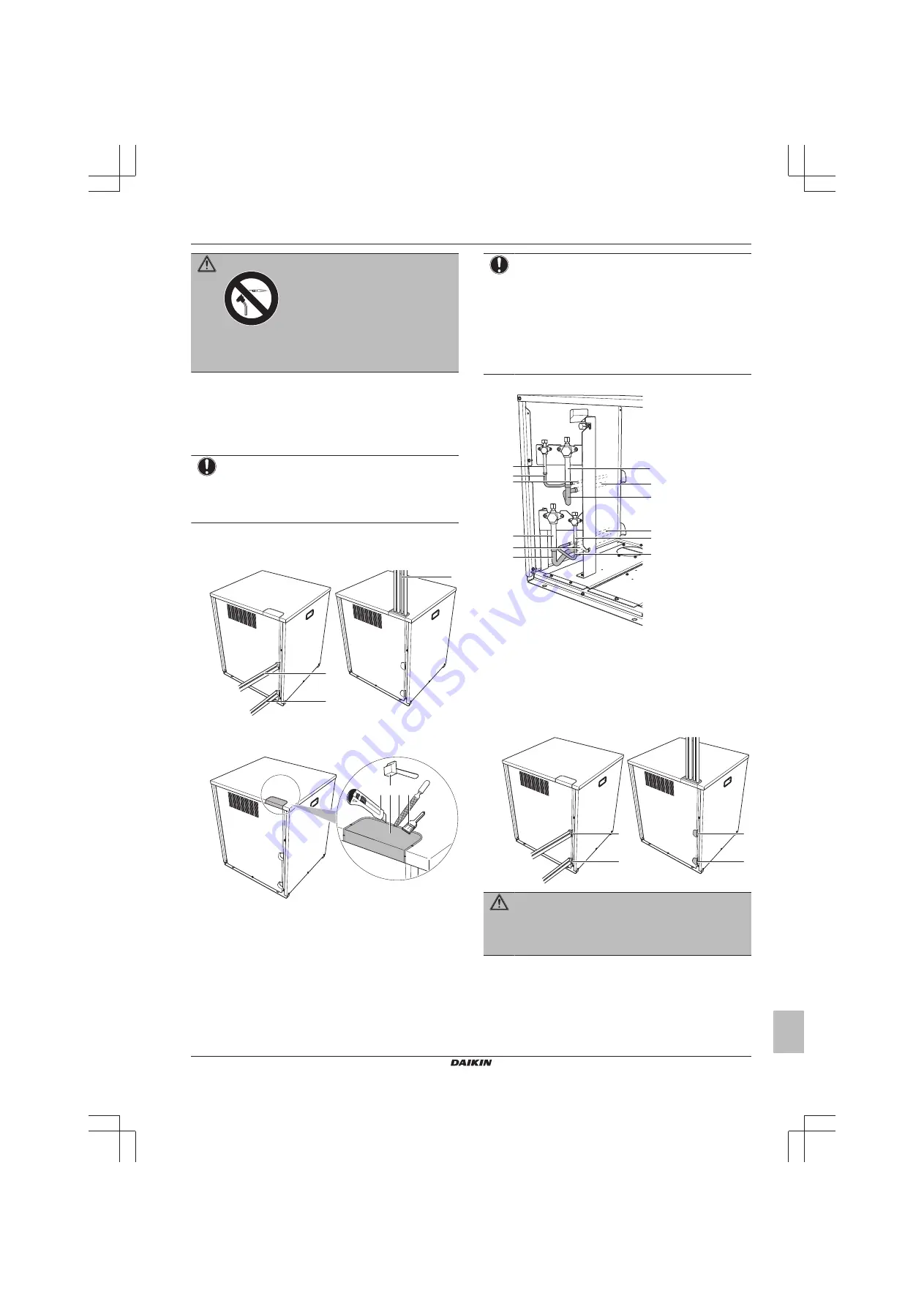
Choose a piping route (a or b).
b
a
a
a
To the back
b
To the top
3
If you have chosen the piping route to the top:
a b c d
a
Cut the insulation (under the knockout hole).
b
Hit on the knockout hole, and remove it.
c
Remove the burrs.
d
Paint the edges and areas around the edges using repair
paint to prevent rusting.
NOTICE
Precautions when making knockout holes:
▪ Avoid damaging the casing.
▪ After making the knockout holes, we recommend you
remove the burrs and paint the edges and areas
around the edges using repair paint to prevent rusting.
▪ When passing electrical wiring through the knockout
holes, wrap the wiring with protective tape to prevent
damage.
4
Connect piping (by brazing) as follows:
a1
c1
c2
c3
a2
a3
b1
b2
b3
d3
d1
d2
a
Liquid line (circuit 2: to indoor units)
b
Gas line (circuit 2: to indoor units)
c
Gas line (circuit 1: to heat exchanger unit)
d
Liquid line (circuit 1: to heat exchanger unit)
1
Pinched piping
2
Piping accessory
3
Field piping
5
Reattach the service cover.
6
Seal all gaps (example: a) to prevent small animals from
entering the system.
a
a
a
a
WARNING
Provide adequate measures to prevent that the unit can be
used as a shelter by small animals. Small animals that
make contact with electrical parts can cause malfunctions,
smoke or fire.


