5 Installation
Installation and operation manual
13
RKXYQ5T7Y1B
VRV IV compressor unit for indoor installation
4P408443-1 – 2015.07
Stage 2: Manual charging
(= charging in the "Manual additional refrigerant charge" mode)
Summary – Manual charging
:
Refrigerant bottle
Connected to the service port for refrigerant
charge.
This charges to both circuits, and to the
compressor unit's internal refrigerant piping.
Stop valves
Open
Compressor
Operates
5
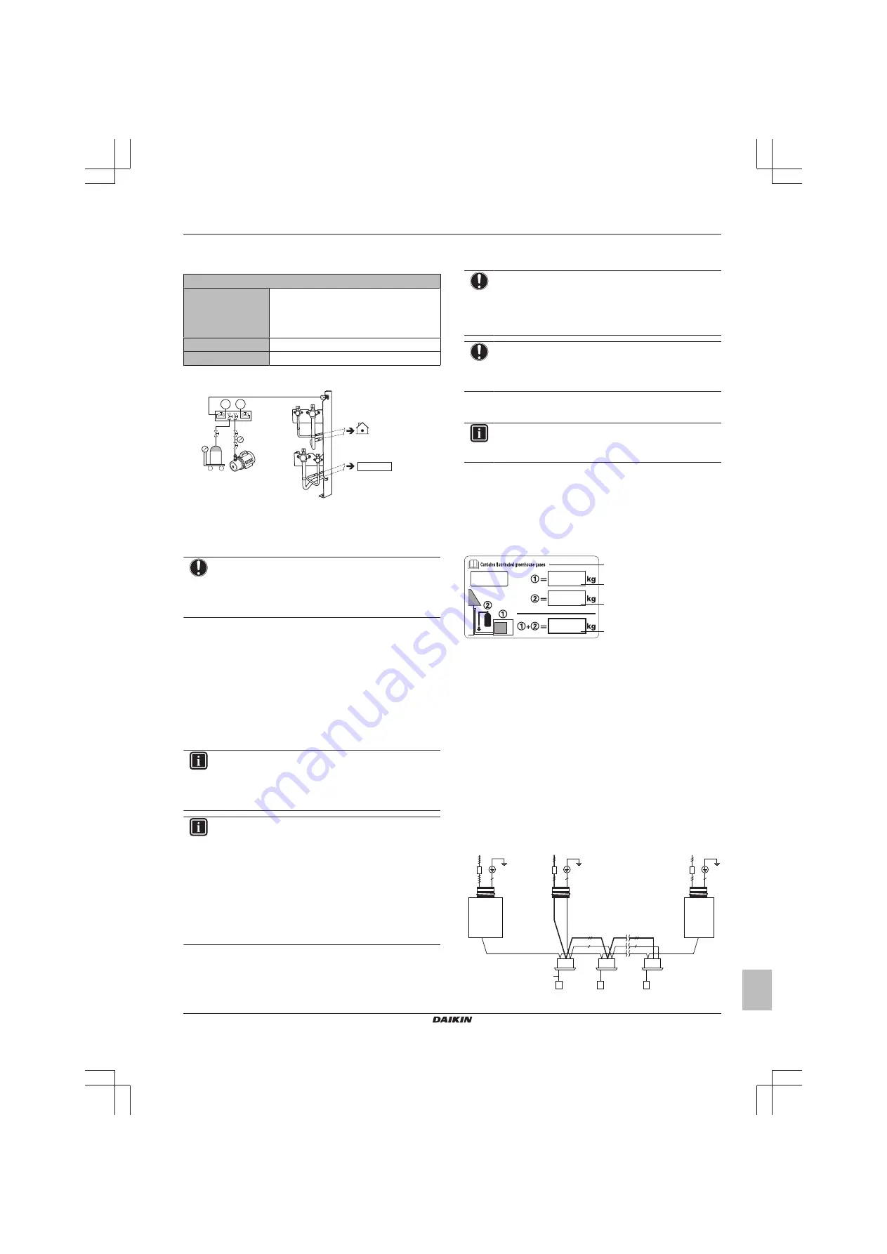
Connect as shown. Make sure valve A is closed.
p< p>
R410A
a
c
b
A
e
d
a
Weighing scales
b
Refrigerant R410A tank (siphon system)
c
Vacuum pump
d
Refrigerant charge port
e
Heat exchanger unit
A
Valve A
NOTICE
The refrigerant charging port is connected to the piping
inside the unit. The unit's internal piping is already factory
charged with refrigerant, so be careful when connecting
the charge hose.
6
Open all compressor unit stop valves. At this point, valve A
must remain closed!
7
Take all the precautions mentioned in
into account.
8
Turn on the power of the indoor units, compressor unit and heat
exchanger unit.
9
Activate setting [2‑20] to start the manual additional refrigerant
charge mode. For details, see
"6.1.8 Mode 2: Field settings" on
.
Result:
The unit will start operation.
INFORMATION
The manual refrigerant charge operation will automatically
stop within 30 minutes. If charging is not completed after
30 minutes, perform the additional refrigerant charging
operation again.
INFORMATION
▪ When a malfunction is detected during the procedure
(e.g., in case of closed stop valve), a malfunction code
will be displayed. In that case, refer to
codes when charging refrigerant" on page 13
solve the malfunction accordingly. Resetting the
malfunction can be done by pushing BS3. You can
restart the "Charging" instructions.
▪ Aborting the manual refrigerant charge is possible by
pushing BS3. The unit will stop and return to idle
condition.
10
Open valve A.
11
Charge refrigerant until the remaining determined additional
refrigerant amount is added, and then close valve A.
12
Press BS3 to stop the manual additional refrigerant charge
mode.
NOTICE
Make sure to open all stop valves after (pre-) charging the
refrigerant.
Operating with the stop valves closed will damage the
compressor.
NOTICE
After adding the refrigerant, do not forget to close the lid of
the refrigerant charging port. The tightening torque for the
lid is 11.5 to 13.9 N•m.
5.6.4
Error codes when charging refrigerant
INFORMATION
If a malfunction occurs, the error code is displayed on the
user interface of the indoor unit.
If a malfunction occurs, close valve A immediately. Confirm the
malfunction code and take corresponding action,
problems based on error codes" on page 22
5.6.5
To fix the fluorinated greenhouse gases
label
1
Fill in the label as follows:
d
c
b
a
a
From the multilingual fluorinated greenhouse gases label
peal off the applicable language and stick it on top of
a
.
b
Factory refrigerant charge: see unit name plate
c
Additional refrigerant amount charged
d
Total refrigerant charge
2
Fix the label on the inside of the compressor unit. There is a
dedicated place for it on the wiring diagram label.
5.7
Connecting the electrical wiring
5.7.1
Field wiring: Overview
Field wiring consists of:
▪ Power supply (always including earth)
▪ Communication (= transmission) wiring between the compressor
unit, the heat exchanger unit, and the indoor units.
Example:
g
f
F1/F2
(16 V)
F1/F2
(16 V)
220-240 V
1~ 50 Hz
e
c
a
d
b
220-240 V
1~ 50 Hz
380-415 V
3N~ 50 Hz
a
Main switch


