22
FA ROTEX Solaris RPS4 -
04/2016
6
x
FlowSensor
6.2.8 Output calculation, maximum values, and yield
count
If a FlowSensor is connected, the system operating data is calcu-
lated and balanced, such as the current heat output and the solar
heat yield. The maximum and calculated values can be shown on
the display (see chapter 6.3). Values greater than "0" which have
not been deleted are still displayed after disconnecting or disa-
bling the FlowSensors (without further updating).
6.2.9 Speed regulation of the solar operating pump
P
S
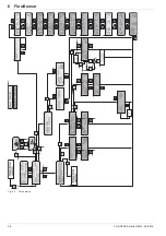
After reaching the switch-on conditions, the Solaris R4 regulator
activates:
– the actuation of the solar operating pump P
S
at full output for
filling the solar system. This takes place dependent on the set
parameter value [time P2] in [secs].
Î
If the correctly adjusted FlowSensor detects a steady flow
before this time has expired, the solar system is com-
pletely filled with water.
– the actuation of the solar operating pump P
S
at full output up
to possible maximum flow rate of the system.
– the stepless output reduction of the solar operating pump P
S
,
until the calculated target spread "DT" maintains the set value
in accordance with fig. 6-2, or until the flow rate falls below the
minimum flow rate V2 (fig. 6-3 and tab. 6-1).
– the stepless increase in output of the solar operating pump P
S
after a safety period "t
2
" (fig. 6-3).
Switches the pump to the next output stage after a safety period
t2 has elapsed (fig. 5-3). If the flow rate falls below the value "V2"
(fig. 6-3 and tab. 6-1), the controller detects a flow rate
breakaway, the last valid output stage is saved as the minimum
pump output value. Lower pump output stages are automatically
blocked.
The temperature-dependent output regulation of the solar oper-
ating pump P
S
then takes place between the determined
minimum and maximum outputs. The spread of "T
V
" and "T
R
"
(=T
V
– T
R
) is measured continuously and compared with the
target spread "DT". If the temperature spread between "T
V
" and
"T
R
" is too great, the pump output (max. 15 stages) and thus also
the flow rate through the solar panel is increased until the target
spread is achieved. If the spread is too small, the pump output is
reduced (fig. 6-2). The current pump output is displayed during its
active running time in the operating display [Flow rate], next to the
throughput measured value in percent. A typical operating se-
quence of a modulating solar system is shown in fig. 6-3.
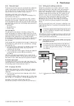
Fig. 6-2
Pump output control as a function of temperature difference
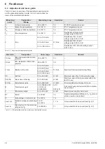
FlowSensorType
Parameter value
[FLS active]
Minimum flow
Start phase "V1" in l/min
Minimum flow
operating phase "V2" in l/min
As required
0
FLS deactivated - no flow rate
FLS 12 (
on request)
12
1.5
1,0
FLS 20
(included in scope of supply)
20*
2.0
1.5
FLS 100 (
on request)
100
10.0
5.5
Tab. 6-1 Overview of FlowSensors
*automatically set value with detected FlowSensor
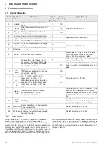
The balancing and calculation of the system operating
data (e.g. solar heat yield) does not replace a calibrated
thermal energy meter. These values may not be used
for invoicing heating costs or similar legally valid
account-ing purposes.
DT
Target spread (calculated for the operating point)
P
S
Solar operating pump
S1
Upper target spread ([delta T 1])
S2
Lower target spread ([delta T 2])
T
K
Collector temperature
T1
Frost protection temperature ([T frost])
T2
Booster temperature ([TK max])
T3
Switch on again protection temperature ([TK permitted])
—
Target spread
- -
Switching limits for pump modulation
n
Pump output is increased
p
Pump output is reduced
Controller is switched off and back on again:
– automatically blocked pump stages are released again.
– the system is automatically regulated again.
– manually blocked pump stages (see chapter 6.3.8) remain
blocked.


