SiBE341001
Troubleshooting by Remote Controller
Troubleshooting
104
k
: ON
h
: OFF
l
: Blink
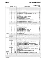
Malfunction
code
Operation
lamp
Malfunction contents
Page
Referred
Outdoor Unit
E1
l
PCB defect
110
E2
l
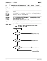
Actuation of high pressure switch
111
E3
l
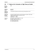
Actuation of high pressure switch
112
E4
l
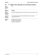
Actuation of low pressure sensor
114
E5
l
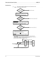
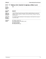
Inverter compressor motor lock
116
E7
l
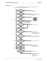
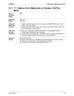
Malfunction of outdoor unit fan motor
118
E9
l
Malfunction of moving part of electronic expansion valve (Y1E ~ Y5E)
121
F3
l
Abnormal discharge pipe temperature
123
F4
l
Humidity alarm
125
F9
l
Malfunction of BS unit electronic expansion valve
127
H7
l
Abnormal outdoor fan motor signal
129
H9
l
Malfunction of thermistor (R1T) for outdoor air
131
J3
l
Malfunction of discharge pipe thermistor (R31T, R32T, R33T)
132
J4
l
Malfunction of temperature sensor for heat exchanger gas (R2T or R11T)
132
J5
l
Malfunction of thermistor (R8T or R10T) for suction pipe
132
J6
l
Malfunction of thermistor (R4T or R12T) for outdoor unit heat exchanger
132
J7
l
Malfunction of liquid pipe thermistor 1 (R6T, R9T or R14T)
132
J8
l
Malfunction of liquid pipe thermistor 2 (R7T or R15T)
132
J9
l
Malfunction of subcooling heat exchanger gas pipe thermistor (R5T or
R13T)
132
JA
l
Malfunction of high pressure sensor
134
JC
l
Malfunction of low pressure sensor
136
L1
l
Malfunction of inverter PCB
138
L4
l
Malfunction of inverter radiating fin temperature rise
140
L5
l
Momentary overcurrent of inverter compressor
142
L8
l
Momentary overcurrent of inverter compressor
144
L9
l
Inverter compressor starting failure
146
Outdoor Unit
LA
l
Malfunction of power unit
—
LC
l
Malfunction of transmission between inverter and control PCB
149
P1
l
Inverter over-ripple protection
151
P4
l
Malfunction of inverter radiating fin temperature rise sensor
153
PJ
l
Faulty field setting after replacing main PCB or faulty combination of PCB
154
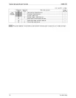
System
U1
l
Reverse phase, open phase
156
U2
l
Power supply insufficient or instantaneous failure
157
U3
l
Check operation not executed
160
U3
k
Check operation is not completed.
160
U4
l
Malfunction of transmission between indoor units and outdoor units
162
U7
l
Transmission failure (Across outdoor units)
165
U8
l
Malfunction of transmission between main and sub remote controllers
172
U9
l
Malfunction of transmission between indoor and outdoor units in the same
system
173
UA
l
Improper combination of indoor and outdoor units, indoor units and remote
controller
174
UC
k
Address duplication of centralized controller
182
UE
l
Malfunction of transmission between centralized controller and indoor unit
183
UF
l
System is not set yet
186
UH
l
Malfunction of system, refrigerant system address undefined
187
Centralized
Remote
Controller
and
Schedule
Timer
M1
k
or
h
PCB defect
—
M8
k
or
h
Malfunction of transmission between optional controllers for centralized
control
—
MA
k
or
h
Improper combination of optional controllers for centralized control
—
MC
k
or
h
Address duplication, improper setting
—
Summary of Contents for RQYQ140-180PY1
Page 216: ...Piping Diagrams SiBE341001 207 Appendix 1 2 BS Unit BSVQ100 160 250PV1 4D057985B...
Page 217: ...SiBE341001 Piping Diagrams Appendix 208 BSV4Q100PV1 3D064148...
Page 218: ...Piping Diagrams SiBE341001 209 Appendix BSV6Q100PV1 3D064149...
Page 220: ...Wiring Diagrams for Reference SiBE341001 211 Appendix 2 2 BS Unit BSVQ100 160 250PV1 3D055928C...
Page 221: ...SiBE341001 Wiring Diagrams for Reference Appendix 212 BSV4Q100PV1 3D063928B...
Page 222: ...Wiring Diagrams for Reference SiBE341001 213 Appendix BSV6Q100PV1 3D063929B...
Page 223: ...SiBE341001 Option List Appendix 214 3 Option List 3 1 Option Lists Outdoor Unit 3D066354...

