SiBE341001
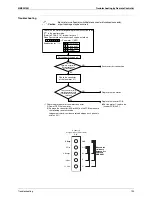
Troubleshooting by Remote Controller
Troubleshooting
116
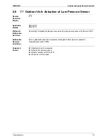
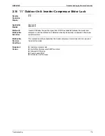
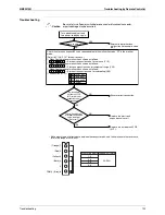
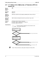
2.10
“
E5
”
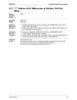
Outdoor Unit: Inverter Compressor Motor Lock
Remote
Controller
Display
E5
Applicable
Models
RQYQ-PY1
RQEQ-PY1
Method of
Malfunction
Detection
Inverter PCB takes the position signal from UVW line connected between the inverter and
compressor, and the malfunction is detected when any abnormality is observed in the phase-
current waveform.
Malfunction
Decision
Conditions
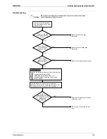
This malfunction will be output when the inverter compressor motor does not start up even in
forced startup mode.
Supposed
Causes
Inverter compressor lock
High differential pressure (0.5MPa or more)
Incorrect UVW wiring
Faulty inverter PCB
Stop valve is left in closed
Summary of Contents for RQYQ140-180PY1
Page 216: ...Piping Diagrams SiBE341001 207 Appendix 1 2 BS Unit BSVQ100 160 250PV1 4D057985B...
Page 217: ...SiBE341001 Piping Diagrams Appendix 208 BSV4Q100PV1 3D064148...
Page 218: ...Piping Diagrams SiBE341001 209 Appendix BSV6Q100PV1 3D064149...
Page 220: ...Wiring Diagrams for Reference SiBE341001 211 Appendix 2 2 BS Unit BSVQ100 160 250PV1 3D055928C...
Page 221: ...SiBE341001 Wiring Diagrams for Reference Appendix 212 BSV4Q100PV1 3D063928B...
Page 222: ...Wiring Diagrams for Reference SiBE341001 213 Appendix BSV6Q100PV1 3D063929B...
Page 223: ...SiBE341001 Option List Appendix 214 3 Option List 3 1 Option Lists Outdoor Unit 3D066354...

