Troubleshooting by Remote Controller
SiBE341001
191
Troubleshooting
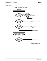
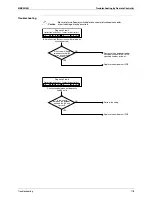
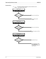
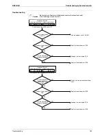
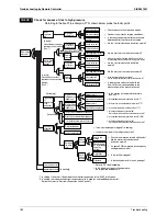
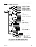
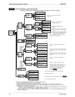
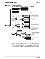
Check the Factors of Overheat Operation
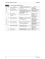
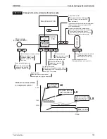
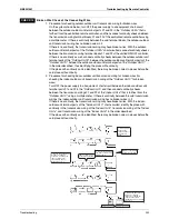
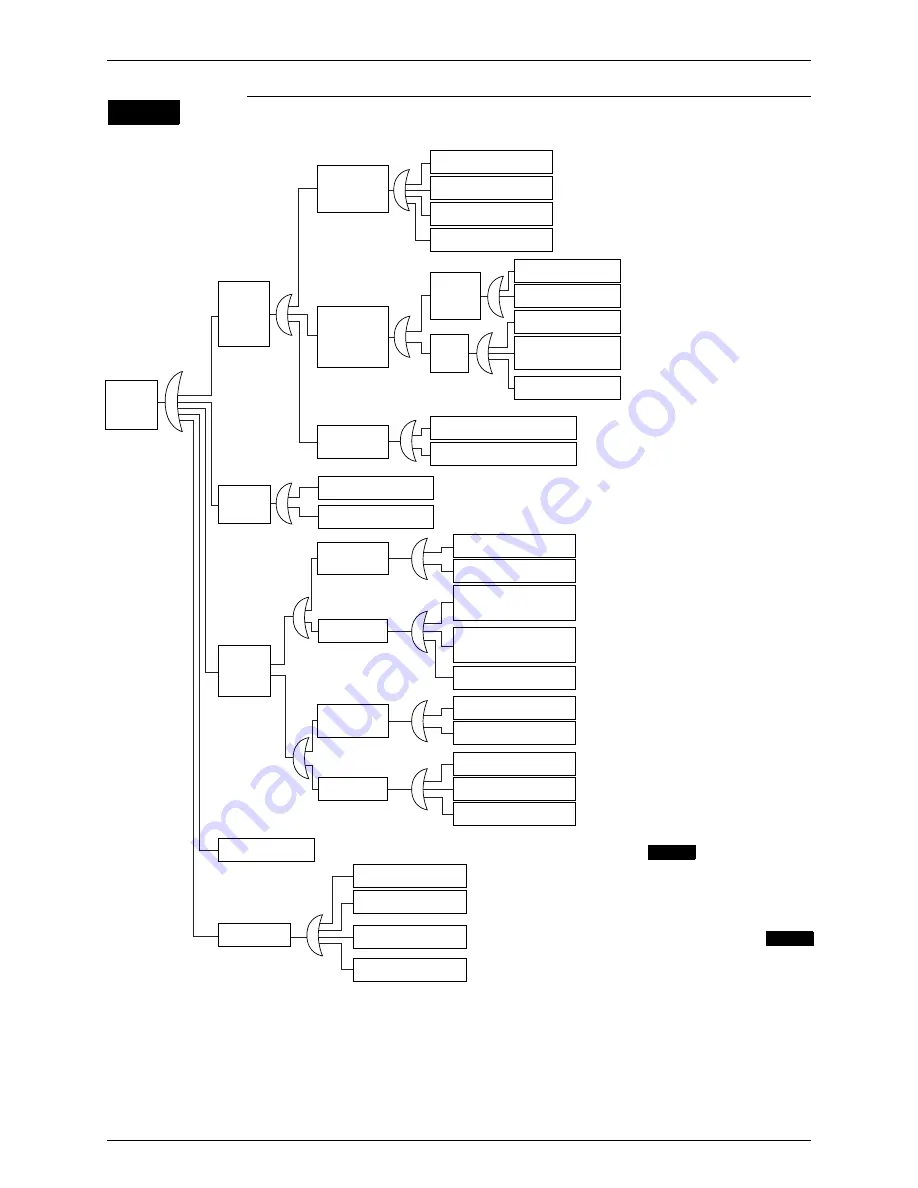
Identify the defective points referring to the failure factor analysis (FTA) as follows.
CHECK 3
Temperature
increase of
discharge
pipe
Faulty
discharge
pipe
temperature
control
Compressor
overheat
[In cooling mode]
If the indoor unit
electronic
expansion valve
is excessively
throttled. (*3)
Faulty
superheated
degree
control.
[In heading
mode] If the
outdoor unit
electronic
expansion valve
is excessively
throttled. (
∗
4)
Refrigerant gas
shortage
Large resistance
of piping
Faulty hot
gas bypass
control
(
∗
1)
[In cooling mode only]
Faulty
subcooling
electronic
expansion valve
control (EV2)
(
∗
2)
Faulty of four
way valve
operation
Superheat due to
shaft damage
Superheat due to
defective compressor
Indoor unit
electronic expansion
valve failure
Faulty control
Outdoor unit
electronic expansion
valve failure
Faulty control
Irregular piping length
Bend/collapse
(Including moisture choke)
Stop valve is closed.
Hot gas circuit clogging
Defective solenoid
valve coil
Defective solenoid
valve body
Defective control PCB
Subcooling
electronic
expansion
valve failure
Control
failure
Defective valve coil
Defective valve
body
Defective low
pressure sensor
Defective subcooling
heat exchanger outlet
thermistor
Defective control
PCB
Four way valve is in the
middle position.
Leak from hot gas bypass
valve
Defective valve coil
Defective valve body
Defective thermistor for
indoor unit gas pipe
Defective thermistor for
indoor unit liquid pipe
Defective control PCB
Defective valve coil
Defective valve body
Defective low pressure
sensor
Defective thermistor for
suction pipe
Defective control PCB
←
Check if coil resistance and insulation
are normal.
←
Check if coil resistance and
insulation are normal.
←
Check if the voltage property is
normal.
←
Check if the connector is connected properly.
Check if the thermistor resistance property is
normal.
←
Check if the pressure value given by the
service checker corresponding to actual
measurement value by the sensor.
←
Check if the piping temperature connected
to the four way valve is normal.
←
Check if coil resistance and insulation are
normal.
←
Check if the connector is connected properly.
Check if the thermistor resistance property is
normal.
←
Check if the connector is connected properly.
Check if the thermistor resistance property is
normal.
←
Check if coil resistance and insulation are
normal.
←
Check if the voltage property is normal.
←
Check if the connector is connected properly.
Check if the thermistor resistance property is normal.
←
Check if the pressure value given by the
service checker corresponding to actual
measurement value by the sensor.
←
Refer to
←
Does the piping length fall in the permissible range?
←
Conduct visual checks.
←
Remove the moisture by vacuum break. (Refer to )
←
Check if the stop valve is open.
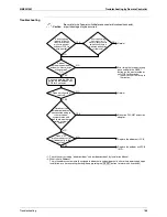
∗
1: Refer to “Low pressure protection control” for hot gas bypass control.
∗
2: Refer to “Subcooling electronic expansion valve control”.
∗
3: “Superheating temperature control” in cooling mode is conducted by indoor unit electronic expansion valve.
∗
4: Superheating temperature control in heating mode is conducted by outdoor unit electronic expansion valve (EVM).
∗
5: Judgement criteria of superheat operation:
(1) Suction gas superheating temperature: 10 degrees and over. (2) Discharge gas superheating temperature: 45 degrees
and over, except for immediately after starting and drooping control, etc..
(Use the above stated values as a guide. Depending on the other conditions, the unit may be normal despite the values
within the above scope.)
CHECK 7
CHECK 8
Summary of Contents for RQYQ140-180PY1
Page 216: ...Piping Diagrams SiBE341001 207 Appendix 1 2 BS Unit BSVQ100 160 250PV1 4D057985B...
Page 217: ...SiBE341001 Piping Diagrams Appendix 208 BSV4Q100PV1 3D064148...
Page 218: ...Piping Diagrams SiBE341001 209 Appendix BSV6Q100PV1 3D064149...
Page 220: ...Wiring Diagrams for Reference SiBE341001 211 Appendix 2 2 BS Unit BSVQ100 160 250PV1 3D055928C...
Page 221: ...SiBE341001 Wiring Diagrams for Reference Appendix 212 BSV4Q100PV1 3D063928B...
Page 222: ...Wiring Diagrams for Reference SiBE341001 213 Appendix BSV6Q100PV1 3D063929B...
Page 223: ...SiBE341001 Option List Appendix 214 3 Option List 3 1 Option Lists Outdoor Unit 3D066354...

