SiBE341001
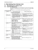
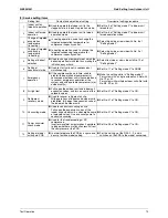
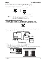
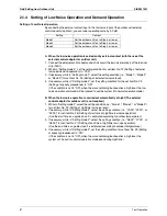
Field Setting from Outdoor Unit
Test Operation
72
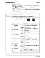
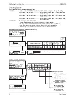
Setting by push button switches
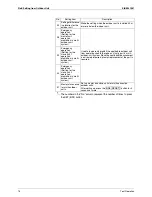
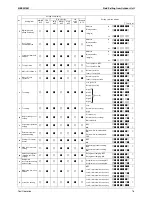
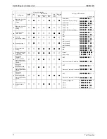
The following settings are made by push button switches on PCB.
In case of multi-outdoor unit system, various items should be set with the master unit.
(Setting with the slave unit is disabled.)
(Factory setting)
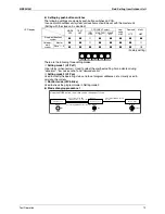
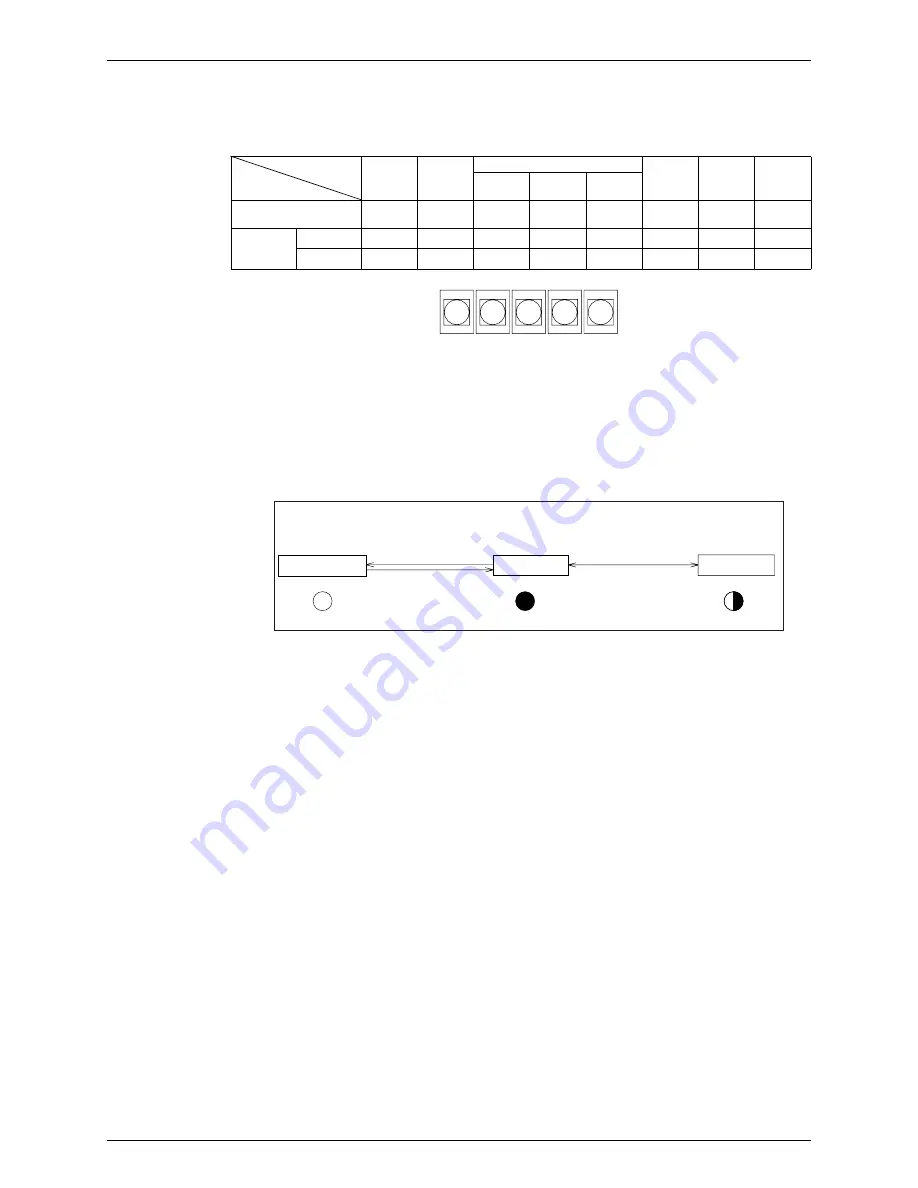
There are the following three setting modes.
c
Setting mode 1 (H1P off)
Initial status (when normal) : Used to select the cool/heat setting. Also indicates during
“abnormal”, “low noise control” and “demand control”.
d
Setting mode 2 (H1P on)
Used to modify the operating status and to set program addresses, etc. Usually used in
servicing the system.
e
Monitor mode (H1P blinks)
Used to check the program made in Setting mode 2.
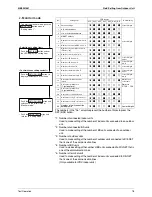
Mode changing procedure 1
LED display
MODE
H1P
TEST
H2P
COOL/HEAT select
Low
noise
H6P
Demand
H7P
Multi;
H8P
IND
H3P
MASTER
H4P
SLAVE
H5P
Single-outdoor-unit
system
h
h
k
h
h
h
h
h
Outdoor-
multi
system
Master
h
h
k
h
h
h
h
k
Slave 1 ~ 4
h
h
h
h
h
h
h
l
BS1
MODE
BS2
SET
BS3
RETURN
BS4
TEST
BS5
RESET
Setting mode 1
Monitor mode
H1P
Push the BS1(MODE button)
one time.
Blinking
MODE
MODE
Off
H1P
Setting mode 2
MODE
On
H1P
Push and hold the BS1
(MODE button) for 5 seconds.
Push the BS1(MODE button) one time.
(Normal)
Using the MODE button, the modes can be changed as follows.
Summary of Contents for RQYQ140-180PY1
Page 216: ...Piping Diagrams SiBE341001 207 Appendix 1 2 BS Unit BSVQ100 160 250PV1 4D057985B...
Page 217: ...SiBE341001 Piping Diagrams Appendix 208 BSV4Q100PV1 3D064148...
Page 218: ...Piping Diagrams SiBE341001 209 Appendix BSV6Q100PV1 3D064149...
Page 220: ...Wiring Diagrams for Reference SiBE341001 211 Appendix 2 2 BS Unit BSVQ100 160 250PV1 3D055928C...
Page 221: ...SiBE341001 Wiring Diagrams for Reference Appendix 212 BSV4Q100PV1 3D063928B...
Page 222: ...Wiring Diagrams for Reference SiBE341001 213 Appendix BSV6Q100PV1 3D063929B...
Page 223: ...SiBE341001 Option List Appendix 214 3 Option List 3 1 Option Lists Outdoor Unit 3D066354...


