SiBE341001
Field Setting from Outdoor Unit
Test Operation
90
2.1.9 Emergency Operation
If the compressor cannot operate, this control inhibits any applicable compressor or outdoor unit
from operating to perform emergency operation only with the operative compressor or outdoor
unit.
[Automatic backup operation]
With multi-outdoor-unit system, if a certain outdoor unit system malfunctions (i.e., the system
stops and indoor unit remote controller displays the malfunction), by resetting the indoor unit
remote controller, the applicable outdoor unit is inhibited from operating for 8 hours, thus
making it possible to perform emergency operation automatically.
However, in the event any of the following malfunctions occurs, automatic backup operation can
be performed.
Malfunctions under which automatic backup operation can be performed:
• E3, E4, E5, E7
• F3
• H7, H9
• J2, J3, J5, J6, J7, J9, JA, JC
• L1, L4, L5, L8, L9, LC
• U2, UJ
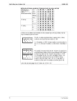
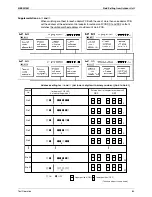
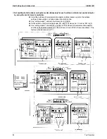
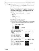
[Emergency operation with settings in service mode]
∗
“Inhibition of operation” is set with each outdoor unit.
Make the following settings with the master unit. (Setting with the slave unit becomes disabled.)
∗
Discriminate the operating status of the master unit / slave units through the following LED
display.
• In order to set the master unit to operation
prohibition mode, set No. 38 of Setting mode 2 to
"MASTER OPERATION PROHIBITION".
(Procedure)
(1) Press and hold the MODE button (BS1) for a period
of 5 seconds or more.
(2) Press the SET button (BS2) 38 times.
(3) Press the RETURN button (BS3) once.
(4) Press the SET button (BS2) once.
(5) Press the RETURN button (BS3) twice.
(6) Press the MODE button (BS1) once.
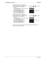
• In order to set the slave unit 1 to operation
prohibition mode, set No. 39 of Setting mode 2 to
"SLAVE 1 OPERATION PROHIBITION".
(Procedure)
(1) Press and hold the MODE button (BS1) for a period
of 5 seconds or more.
(2) Press the SET button (BS2) 39 times.
(3) Press the RETURN button (BS3) once.
(4) Press the SET button (BS2) once.
(5) Press the RETURN button (BS3) twice.
(6) Press the MODE button (BS1) once.
LED display (
h
:ON
h
h
:OFF
l
:Blink)
H1P----H7P H8P
(Factory set)
Master:
Slave 1:
Slave 2:
Slave 3:
hh
hhhhhhh
hhhh
h
hhhhhhh
hhhhhhh
l
hhhhhhh
hhhhhhh
l
hhhhhhh
hhhhhhh
l
LED display (
h
:ON
h
h
:OFF
l
:Blink)
H1P----H7P
(Factory set)
h
hhhhhh
hhhhhh
hhhh
hhhhh
h
hhhhhhh
hhhhhh
hhhhhh
hhhhh
l
hhhhhhh
hhhhhh
hh
hhhhhhh
hhhh
LED display (
h
:ON
h
h
:OFF
l
:Blink)
H1P----H7P
(Factory set)
h
hhhhhh
hhhhhh
hhhh
hhhhh
hhhhhhh
hhhhhh
hhhhhh
hhhhh
l
hhhhhhh
hhhhhh
hh
hhhhhhh
hhhh
Summary of Contents for RQYQ140-180PY1
Page 216: ...Piping Diagrams SiBE341001 207 Appendix 1 2 BS Unit BSVQ100 160 250PV1 4D057985B...
Page 217: ...SiBE341001 Piping Diagrams Appendix 208 BSV4Q100PV1 3D064148...
Page 218: ...Piping Diagrams SiBE341001 209 Appendix BSV6Q100PV1 3D064149...
Page 220: ...Wiring Diagrams for Reference SiBE341001 211 Appendix 2 2 BS Unit BSVQ100 160 250PV1 3D055928C...
Page 221: ...SiBE341001 Wiring Diagrams for Reference Appendix 212 BSV4Q100PV1 3D063928B...
Page 222: ...Wiring Diagrams for Reference SiBE341001 213 Appendix BSV6Q100PV1 3D063929B...
Page 223: ...SiBE341001 Option List Appendix 214 3 Option List 3 1 Option Lists Outdoor Unit 3D066354...

