SiUS041829E
Check
Part 6 Service Diagnosis
113
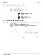
5.2 Indoor Fan Motor Connector Check
Check No.02
1. Check the connection of connector.
2. Check motor power supply voltage output (pins 4 - 7).
3. Check motor control voltage (pins 4 - 3).
4. Check rotation command voltage output (pins 4 - 2).
5. Check rotation pulse input (pins 4 - 1).
5.3 Power Supply Waveform Check
Check No.11
Measure the power supply waveform between No. 1 and No. 2 on the terminal strip, and check the
waveform disturbance.
Check if the power supply waveform is a sine wave (Fig.1).
Check if there is waveform disturbance near the zero-cross (sections circled in Fig.2).
7
6
5
4
3
2
1
S200
Motor power s
u
pply voltage (310 ~ 340 VDC)
Un
u
sed
Un
u
sed
GND
Motor control voltage (15 VDC)
Rotation command voltage (1~ 5 VDC)
Rotation p
u
lse inp
u
t
[Fig.1]
[Fig.2]
(R1736)
(R1444)
Summary of Contents for RX09RMVJU9
Page 17: ...SiUS041829E Part 2 Specifications 13 1 Specifications 14 Part 2 Specifications ...
Page 125: ...SiUS041829E Check Part 6 Service Diagnosis 121 18 class R25105 1 2 3 4 Multimeter ...
Page 127: ...SiUS041829E Check Part 6 Service Diagnosis 123 18 class R20704 W V U DC_P1 DC_N1 ...
Page 143: ...SiUS041829E Operation Limit Part 8 Appendix 139 4 Operation Limit RX09 12 18RMVJU9 3D092209E ...

