SiUS041829E
Table of Contents
ii
3.4 Discharge Pipe Temperature Control......................................................... 50
3.5 Input Current Control.................................................................................. 51
3.6 Freeze-up Protection Control ..................................................................... 52
3.7 Heating Peak-cut Control ........................................................................... 52
3.8 Outdoor Fan Control................................................................................... 53
3.9 Liquid Compression Protection Function.................................................... 53
3.10 Defrost Control ........................................................................................... 54
3.11 Electronic Expansion Valve Control ........................................................... 55
3.12 Malfunctions ............................................................................................... 58
Part 5 Remote Controller ................................................................ 59
1. Applicable Remote Controller ...................................................................60
2. ARC466A36 ..............................................................................................61
Part 6 Service Diagnosis ................................................................. 63
1. General Problem Symptoms and Check Items .........................................65
2. Troubleshooting with LED .........................................................................66
3.1 Method 1 .................................................................................................... 67
3.2 Method 2 .................................................................................................... 68
4.1 Error Codes and Description ...................................................................... 70
4.2 Indoor Unit PCB Abnormality ..................................................................... 71
4.3 Freeze-up Protection Control/Heating Peak-cut Control ............................ 73
4.4 Indoor Fan Motor (DC Motor) or Related Abnormality ............................... 74
4.5 Thermistor or Related Abnormality............................................................. 77
4.6 Front Panel Open/Close Fault.................................................................... 78
4.7 Low-voltage Detection or Over-voltage Detection...................................... 79
4.8 Signal Transmission Error (Between Indoor Unit and Outdoor Unit).......... 81
4.9 Unspecified Voltage (Between Indoor Unit and Outdoor Unit) ................... 83
4.10 Outdoor Unit PCB Abnormality................................................................... 84
4.11 OL Activation (Compressor Overload) ....................................................... 85
4.12 Compressor Lock ....................................................................................... 88
4.13 DC Fan Lock .............................................................................................. 90
4.14 Input Overcurrent Detection ....................................................................... 91
4.15 Four Way Valve Abnormality...................................................................... 93
4.16 Discharge Pipe Temperature Control......................................................... 95
4.17 High Pressure Control in Cooling ............................................................... 96
4.18 System Shutdown due to Temperature Abnormality in Compressor ......... 98
4.19 Compressor System Sensor Abnormality .................................................. 99
4.20 Position Sensor Abnormality .................................................................... 100
4.21 DC Voltage/Current Sensor Abnormality.................................................. 103
4.22 Thermistor or Related Abnormality (Outdoor Unit)................................... 104
4.23 Electrical Box Temperature Rise.............................................................. 106
4.24 Radiation Fin Temperature Rise .............................................................. 107
Summary of Contents for RX09RMVJU9
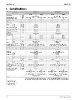
Page 17: ...SiUS041829E Part 2 Specifications 13 1 Specifications 14 Part 2 Specifications ...
Page 125: ...SiUS041829E Check Part 6 Service Diagnosis 121 18 class R25105 1 2 3 4 Multimeter ...
Page 127: ...SiUS041829E Check Part 6 Service Diagnosis 123 18 class R20704 W V U DC_P1 DC_N1 ...
Page 143: ...SiUS041829E Operation Limit Part 8 Appendix 139 4 Operation Limit RX09 12 18RMVJU9 3D092209E ...


