Troubleshooting
SiUS041829E
82
Part 6 Service Diagnosis
Reference
Troubleshooting
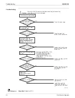
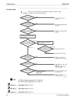
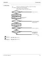
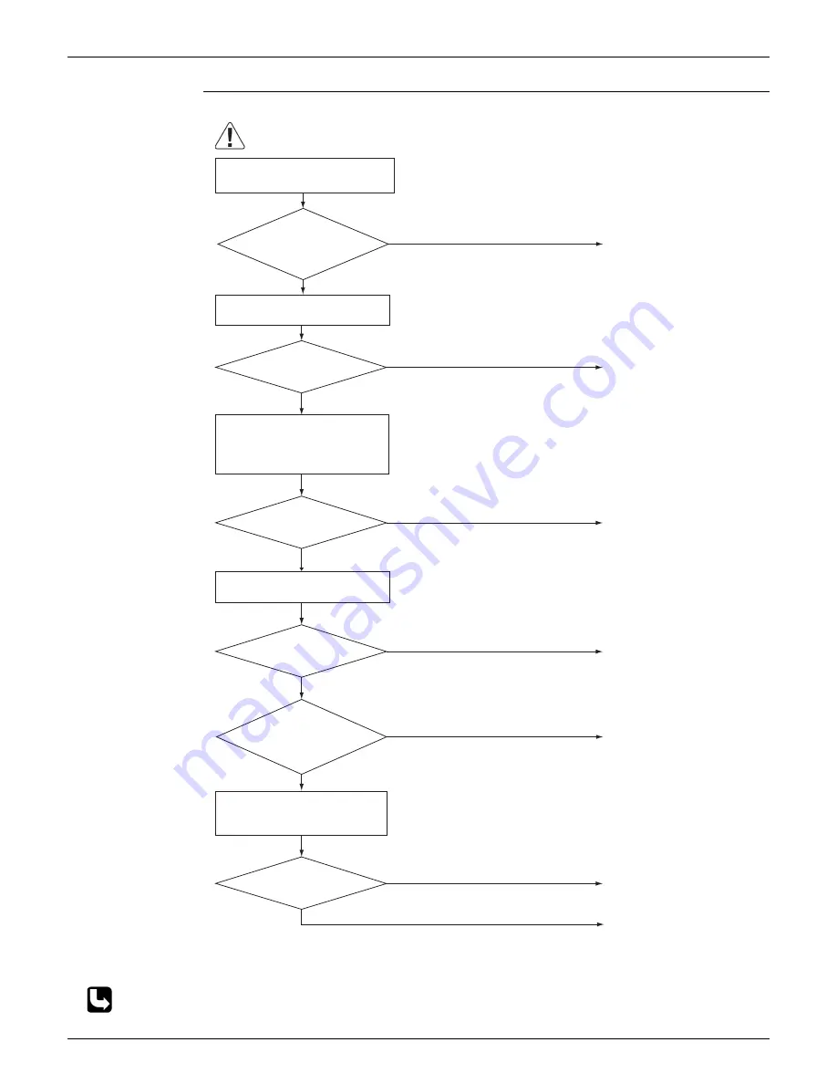
Check No.11
Check No.11
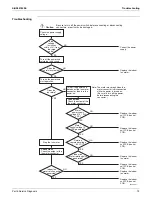
Check the power s
u
pply
waveform.
Check the voltage of the
connection wires on the indoor
terminal board between No. 1
and No. 3, and between No. 2
and No. 3.
YES
Blink
Replace the indoor
u
nit PCB
(control PCB).
Locate the ca
u
se of the
dist
u
rbance of the power
s
u
pply waveform, and correct
it.
NO
(R21199)
Contin
u
o
u
sly ON or OFF
NO
YES
YES
NO
Caution
Correct the indoor
u
nit -
o
u
tdoor
u
nit connection wires.
Replace the o
u
tdoor
u
nit PCB
(main PCB).
Replace the connection wires
between the indoor
u
nit and
o
u
tdoor
u
nit.
Is LED A blinking?
Properly ins
u
lated?
Is there any dist
u
rbance?
Is there any wiring error?
Check the indoor
u
nit - o
u
tdoor
u
nit connection wires.
Check the LED A on the o
u
tdoor
u
nit PCB.
Be s
u
re to t
u
rn off the power switch before connecting or disconnecting
connectors, or parts may be damaged.
∗
Before yo
u
check the LED A, cancel
the standby electricity saving
f
u
nction by starting fan operation
with the remote controller.
∗
Wait at least for 7 sec. after t
u
rning
on the power.
NO
YES
Check the power s
u
pply voltage.
Correct the power s
u
pply.
YES
NO
Replace the o
u
tdoor fan motor
and the o
u
tdoor
u
nit PCB
(main PCB).
Rotate the
o
u
tdoor fan by hand.
Does the o
u
tdoor fan rotate
smoothly?
Is the voltage
fl
u
ct
u
ation within ±10%
from the rated val
u
e?
Summary of Contents for RX09RMVJU9
Page 17: ...SiUS041829E Part 2 Specifications 13 1 Specifications 14 Part 2 Specifications ...
Page 125: ...SiUS041829E Check Part 6 Service Diagnosis 121 18 class R25105 1 2 3 4 Multimeter ...
Page 127: ...SiUS041829E Check Part 6 Service Diagnosis 123 18 class R20704 W V U DC_P1 DC_N1 ...
Page 143: ...SiUS041829E Operation Limit Part 8 Appendix 139 4 Operation Limit RX09 12 18RMVJU9 3D092209E ...


