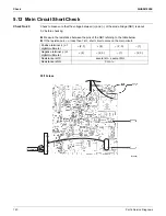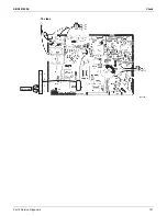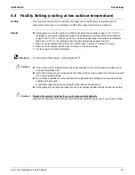
Check
SiUS041829E
122
Part 6 Service Diagnosis
5.13 Power Module Check
Check No.22
Check to make sure that the voltage between (+) and (–) of the power module is about 0 V before
checking.
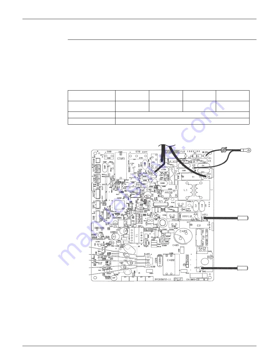
Disconnect the compressor harness connector from the outdoor unit PCB. To disengage the
connector, press the protrusion on the connector.
Follow the procedure below to measure resistance between the terminals of the power module
and the terminals of the compressor with a multimeter. Evaluate the measurement results
referring to the following table.
09/12 class
Positive terminal (+) of
digital multimeter
Power module
(+)
UVW
Power module
(–)
UVW
Negative terminal (–) of
digital multimeter
UVW
Power module
(+)
UVW
Power module
(–)
Resistance is OK.
several k
~ several M
Resistance is NG.
0
or
Pin 24: +
Pin 23: U
Pin 22: V
Pin 21: W
Pin 20: –
(R20703)
Summary of Contents for RX09RMVJU9
Page 17: ...SiUS041829E Part 2 Specifications 13 1 Specifications 14 Part 2 Specifications ...
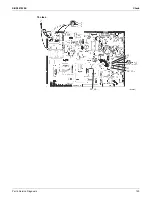
Page 125: ...SiUS041829E Check Part 6 Service Diagnosis 121 18 class R25105 1 2 3 4 Multimeter ...
Page 127: ...SiUS041829E Check Part 6 Service Diagnosis 123 18 class R20704 W V U DC_P1 DC_N1 ...
Page 143: ...SiUS041829E Operation Limit Part 8 Appendix 139 4 Operation Limit RX09 12 18RMVJU9 3D092209E ...

