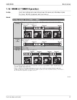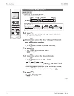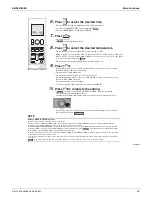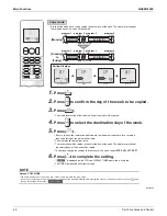
SiUS041829E
Main Functions
Part 4 Functions and Control
25
1.3 Airflow Direction Control
Power-Airflow
Dual Flaps
The large flap sends a large volume of air downward to the floor and provides an optimum control in
cooling, dry and heating operation.
Cooling/Dry
During cooling or dry operation, the flap retracts into the indoor unit. Then, cool air can be blown far
and distributed all over the room.
Heating
During heating operation, the large flap directs airflow downward to spread the warm air to the
entire room.
Wide-Angle
Louvers
The louvers, made of elastic synthetic resin, provide a wide range of airflow that guarantees
comfortable air distribution.
Auto-Swing
The following tables explain the auto-swing process for cooling, dry, heating and fan:
3-D Airflow
Alternative repetition of vertical and horizontal swing motions enables uniform air-conditioning of
the entire room.
When the horizontal swing and vertical swing are both set to automatic operation, the airflow
becomes 3-D airflow. The horizontal and vertical swing motions are alternated and the airflow
direction changes in the order shown in the following diagram.
(1) The vertical blades (louvers) move from the right to the left.
(2) The horizontal blades (flaps) move downward.
(3) The vertical blades (louvers) move from the left to the right.
(4) The horizontal blades (flaps) move upward.
COMFORT
AIRFLOW
Operation
The flaps are controlled not to blow the air directly at the people in the room.
The airflow direction is upward while in cooling operation, and downward while in heating operation.
This function prevents cold or warm air from blowing directly on the occupants in the room.
Flap (up and down)
Louver
(right and left)
Cooling/Dry
Heating
Fan
09/12/18
class
(R23915)
50°
30°
(R23916)
65°
30°
(R21084)
25°
50°
35°
35°
(R21085)
(R19554)
(2)
(4)
(3)
(1)
Summary of Contents for RX09RMVJU9
Page 17: ...SiUS041829E Part 2 Specifications 13 1 Specifications 14 Part 2 Specifications ...
Page 125: ...SiUS041829E Check Part 6 Service Diagnosis 121 18 class R25105 1 2 3 4 Multimeter ...
Page 127: ...SiUS041829E Check Part 6 Service Diagnosis 123 18 class R20704 W V U DC_P1 DC_N1 ...
Page 143: ...SiUS041829E Operation Limit Part 8 Appendix 139 4 Operation Limit RX09 12 18RMVJU9 3D092209E ...


