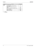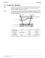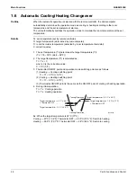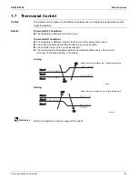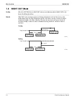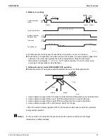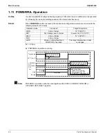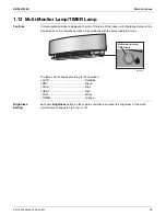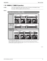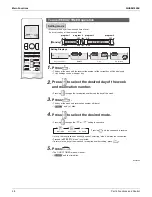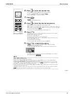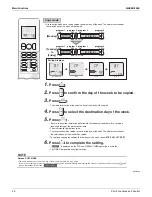
Main Functions
SiUS041829E
26
Part 4 Functions and Control
Note(s)
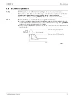
1.4 Fan Speed Control for Indoor Unit
Outline
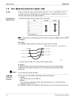
Phase control and fan speed control contains 9 steps: LLL, LL, SL, L, ML, M, MH, H, and HH.
The airflow rate can be automatically controlled depending on the difference between the room
thermistor temperature and the target temperature.
Automatic Fan
Speed Control
In automatic fan speed operation, the step SL is not available.
R4003512
= The airflow rate is automatically controlled within this range when
FAN
setting button is set
to automatic.
Cooling
The following drawing explains the principle of fan speed control for cooling.
The upper limit is at M tap in 30 minutes from the operation start.
Heating
In heating operation, the fan speed is regulated according to the indoor heat exchanger
temperature and the difference between the room thermistor temperature and the target
temperature.
The fan stops during defrost operation.
COMFORT
AIRFLOW
Operation
The fan speed is controlled automatically within the following steps.
Cooling
L tap ~ MH tap (same as AUTOMATIC)
Heating
In order to obtain a comfortable airflow, the fan speed may be set to a rate different from
automatic fan speed control.
POWERFUL operation and COMFORT AIRFLOW operation cannot be used at the same time.
Heating
Cooling
Step
LLL
LL
L
ML
M
MH
H
HH (POWERFUL)
(R21654)
+2.5°C (+4.5°F)
+1.5°C (+2.7°F)
+0.5°C (+0.9°F)
MH*
M
ML
L
+3°C (+5.4°F)
+2°C (+3.6°F)
+1°C (+1.8°F)
Fan speed
Room thermistor temperat
u
re – target temperat
u
re
Summary of Contents for RX09RMVJU9
Page 17: ...SiUS041829E Part 2 Specifications 13 1 Specifications 14 Part 2 Specifications ...
Page 125: ...SiUS041829E Check Part 6 Service Diagnosis 121 18 class R25105 1 2 3 4 Multimeter ...
Page 127: ...SiUS041829E Check Part 6 Service Diagnosis 123 18 class R20704 W V U DC_P1 DC_N1 ...
Page 143: ...SiUS041829E Operation Limit Part 8 Appendix 139 4 Operation Limit RX09 12 18RMVJU9 3D092209E ...

