27
12.6.2 Connection of wiring to terminals
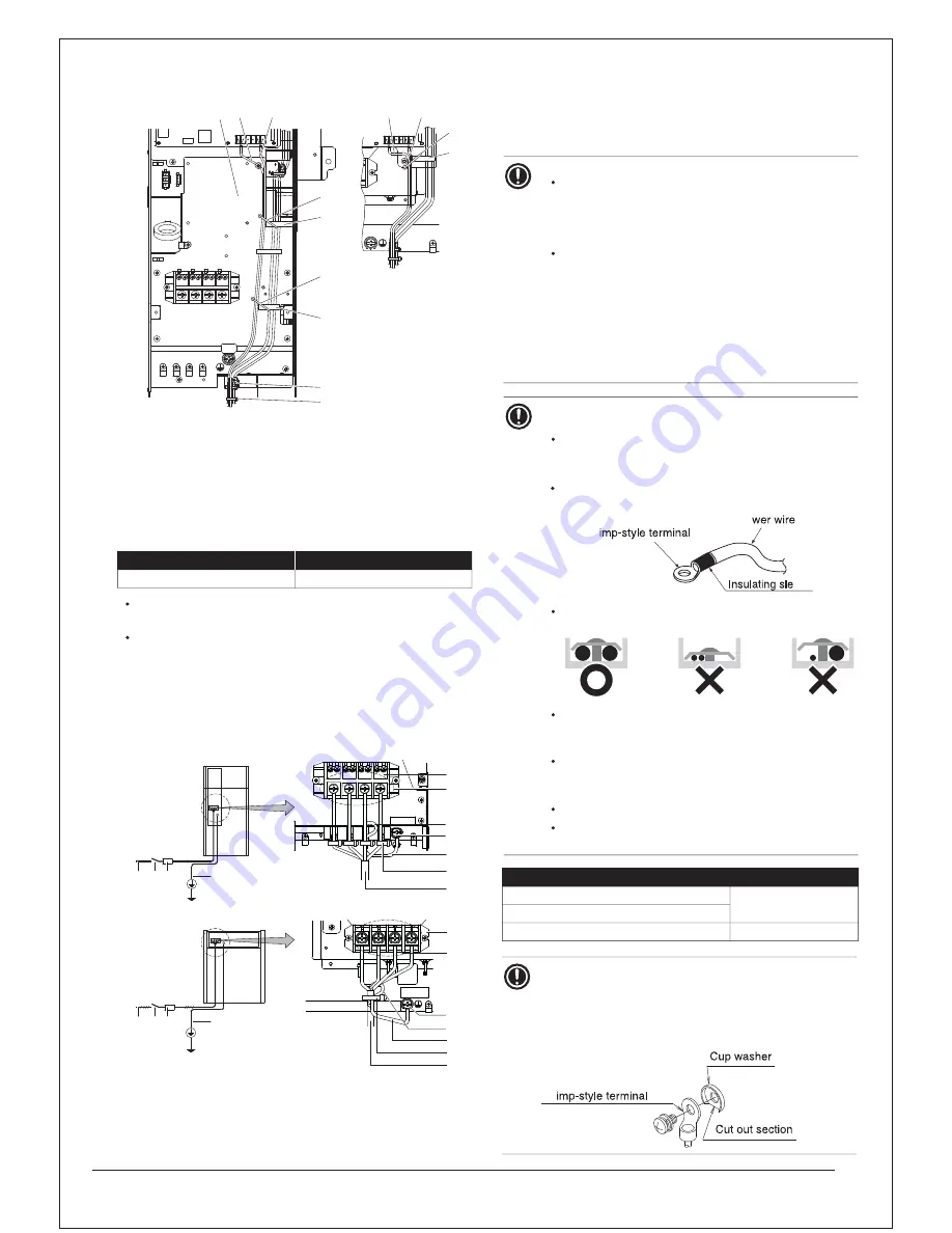
Transmission wiring in outdoor unit
1
Fix to the indicated plastic clamps using field supplied
clamping material
2
Wiring between the units (indoor-outdoor) (F1/F2 left)
3
Internal transmission wiring (Q1/Q2)
4
Plastic clamp
5
Field supplied clamps
Care should be taken for connecting the wires to the terminal block.
See the table below for the tightening torque of the transmission
wiring terminals.
Never connect the power supply to transmission wiring terminal
block. Otherwise the entire system may break down.
Be careful about polarity of the transmission wiring.
Power supply
The power supply must be clamped to the plastic clamp using field
supplied clamp material.
The green and yellow striped wire must be used for earthing only
(refer to the figure below).
1
Power supply (380~415 V - 3N~ 50 Hz / 380 V - 3N~60 Hz)
2
Fuse
3
Earth leakage protector
4
Earth wire
5
Power supply terminal block
6
Connect each power wire: RED to L1, WHT to L2, BLK to
L3 and BLU to N
Screw size
Tightening torque (N
•
m)
0.88±0.08
)
P
1
A
(
5
.
3
M
L1
L2
L3
N
1
4
5
4
5
5
5
4
4
2
3
2
3
1
2
3
4
1
2
3
4
RXQ14~20
RXQ6~12
7
Earth wire (GRN/YLW)
8
Clamp the power supply to the plastic clamp using a
tie wrap (1) to prevent external force being applied to
the terminal.
9
Tie wrap (1)
10
Cup washer
11
When connecting the earth wire, it is recommended to
perform curling.
NOTICE
When routing earth wires, secure clearance of 25 mm
or more away from compressor lead wires. Failure to
observe this instruction properly may adversely affect
correct operation of other units connected to the same
earth.
When connecting the power supply, the earth
connection must be made before the current-carrying
connections are established. When disconnecting the
power supply, the current-carrying connections must
be separated before the earth connection is. The length
of the conductors between the power supply stress relief
and the terminal block itself must be as such that the
current-carrying wires are tautened before the earth wire
is in case the power supply is pulled loose from the
stress relief.
NOTICE
Precautions when laying power wiring:
Do not connect wiring of different thicknesses to the
power terminal block (slack in the power wiring may
cause abnormal heat).
When connecting wiring which is the same thickness,
do as shown in the figure below.
For wiring, use the designated power wire and connect
firmly, then secure to prevent outside pressure being
exerted on the terminal board.
Use an appropriate screwdriver for tightening the terminal
screws. A screwdriver with a small head will damage
the head and make proper tightening impossible.
Over-tightening the terminal screws may break them.
See the table below for tightening torque for the
terminal screws.
Tightening torque (N
•
m)
M8 (Power terminal block)
6.3±0.6
M8 (Ground)
0.88±0.08
)
k
c
o
l
b
l
a
n
i
m
r
e
t
g
n
ir
i
w
t
i
n
u
-r
e
t
n
I(
3.5
M
NOTICE
Recommendations when connecting the earth wire
Wire it so that it comes through the cut out section of the
cup washer. (An improper earth connection may prevent a
good earthing from being achieved.) (See the figure below.)
Be sure to use crimp-style terminal with insulating
sleeves for connections. (See the figure below.)
Po
Cr
eve
Cr
6
8
5
10
11
7
9
6
7
5
10
11
8
9
Summary of Contents for RXQ10AYM
Page 12: ......
Page 28: ...1 T 2 3 4 5 6 NOTICE N 1 2 3 4 5 RXQ6 12 N N N N 8 2 1 6 7 6 6 4 5 4 3 3 6 ...
Page 38: ...Value 2 11 Meaning Level N N N 5 15 2 Mode 2 95 95 5 Value 2 8 Te target 95 95 1 1 N N ...
Page 39: ...959 5 N N 959 1 5 959 9 5 3 3 9 5 9 1 95 9 N 3 3 9 9 9 3 9 3 ...
Page 50: ...5 1 7 RLQW UDQFK LW 53 7 53 7 C D3K05234B Unit mm Unit mm ...
Page 51: ... 53 7 53 7 C D3K05236B Unit mm Unit mm ...
Page 52: ... 53 7 53 7 53 7 53 7 ...
Page 53: ......
Page 56: ... 53 0 53 0 53 0 53 0 ...
Page 57: ......
Page 58: ...5HGXFHU 53 0 73 53 0 3 ...
Page 59: ...2XWGRRU 8QLW 0XOWL RQQHFWLRQ 3LSLQJ LW 3 3 3D052312 Unit mm Gas side Unit mm Liquid side ...
Page 60: ... 3 3 3D052314 Unit mm Gas side Unit mm Liquid side ...
Page 61: ... 3 3 3 3 ...
Page 62: ......
Page 63: ......
Page 64: ......
Page 65: ...5 4 0 5 4 0 5 4 0 5 4 0 ...
Page 66: ......
Page 67: ......
Page 68: ......
Page 69: ...5 4 0 5 4 0 5 4 0 5 4 0 ...
Page 70: ......
Page 71: ......
Page 72: ......
Page 73: ......
Page 74: ......
Page 75: ......
Page 76: ......
Page 77: ......


