4
3. Introduction
3.1
General information
This installation manual concerns the VRV, full inverter driven,
cooling only system.
Depending on the type of outdoor unit which is chosen, some
functionality will or will not exist. It will be indicated throughout this
installation manual and brought to your attention. Certain features
have exclusive model rights.
These units are intended for outdoor installation and aimed for
cooling only applications including air to air applications.
These units have (in single use) cooling capacities rating from 16
to 56 kW. In multi combination cooling on go up till 168 kW.
The outdoor unit is designed to work in cooling mode at ambient
temperatures from 10°C to 49°C.
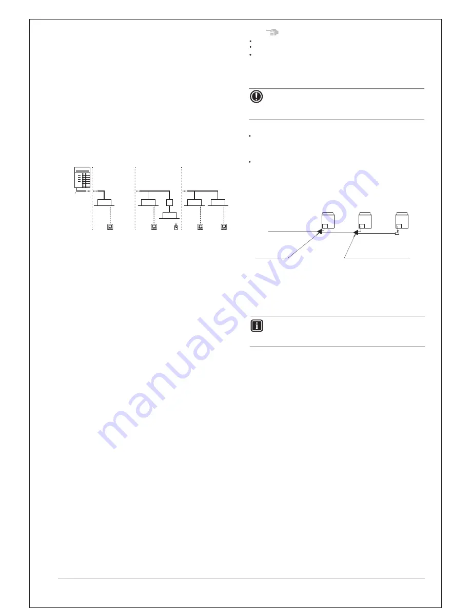
1
VRV Cooling only outdoor unit
2
Refrigerant piping
3
VRV indoor unit
4
BP unit (required to connect Residential Air (RA) indoor units)
5
Residential Air (RA) indoor units
6
User interface (dedicated depending on indoor unit type)
7
User interface (wireless, dedicated depending on indoor
unit type)
6
3
6
7
6
6
3
3
3
5
4
2
1
3.2.
Combination
The indoor units can be installed in the
following range.
(Outdoor unit)
(Combination)
(Total capacity
of indoor units)
RXQ6A
RXQ8A
RXQ10A
RXQ12A
RXQ14A
RXQ16A
RXQ18A/AM
RXQ20A/AM
RXQ22AM
RXQ24AM
RXQ26AM
RXQ28AM
RXQ30AM
RXQ32AM
RXQ34AM
RXQ36AM
RXQ38AM
RXQ40AM
RXQ42AM
RXQ44AM
RXQ46AM
RXQ48AM
RXQ50AM
RXQ52AM
RXQ54AM
RXQ56AM
RXQ58AM
RXQ60AM
75 ~ 195
100 ~ 260
125 ~ 325
150 ~ 390
175 ~ 455
200 ~ 520
225 ~ 585
250 ~ 650
275 ~ 715
300 ~ 780
325 ~ 845
350 ~ 910
375 ~ 975
400 ~ 1,040
425 ~ 1,105
450 ~ 1,170
475 ~ 1,235
500 ~ 1,300
525 ~ 1,365
550 ~ 1,430
575 ~ 1,495
600 ~ 1,560
625 ~ 1,625
650 ~ 1,690
675 ~ 1,755
700 ~ 1,820
725 ~ 1,885
750 ~ 1,950
...........
...........
...........
...........
...........
...........
...........
...........
...........
...........
...........
...........
...........
...........
...........
...........
...........
...........
...........
...........
...........
...........
...........
...........
...........
...........
...........
...........
Single unit
Single unit
Single unit
Single unit,
Single unit,
Single unit
Single unit
Single unit
Multi unit
Multi unit
Multi unit
Multi unit
Multi unit
Multi unit
Multi unit
Multi unit
Multi unit
Multi unit
Multi unit
Multi unit
Multi unit
Multi unit
Multi unit
Multi unit
Multi unit
Multi unit
Multi unit
Multi unit
(a)
Be sure to connect an R410A indoor unit.
See the catalog
Refer to the technical engineering data for multi unit combinations.
for indoor unit models which can be connected.
Outdoor unit can be connected combination in single unit or
multi unit, see more details in the technical engineering data.
Note
NOTICE
When selecting the total capacity higher than mentioned in
above, cooling capacity will drop.
For additional information see technical engineering data.
to indoor unit
Outdoor
unit A
Outdoor
unit B
Outdoor
unit C
Outdoor unit
multi connection
piping kit
(first branch)
Outdoor unit multi
connection piping kit
(second branch)
If the total capacity of the connected indoor units
exceeds the
capacity of the outdoor unit, cooling perfor
mance may drop
when running the indoor units. See the capacity ta
ble in the
Engineering Data Book for details.
There are restrictions on the refrigerant pipe connecting order
betw
een outdoor unit in the case of the multi system
. Install so
that the following restr
ictions are satisfied.
<Restrictions>
The capacities of outdoor units A, B and C m
ust fulfill the
follo
wing conditions.
A
≥
B
≥
C
3.3
Scope of the manual
This manual describes the procedures for handling, installing and
connecting the VRV outdoor units. This manual has been prepared
to ensure adequate maintenance of the unit, and it will provide help in
case problems occur.
INFORMATION
The installation of the indoor unit(s) is described in the indoor
unit installation manual provided with the indoor units.
Multi unit
(a)
Multi unit
(a)
Summary of Contents for RXQ10AYM
Page 12: ......
Page 28: ...1 T 2 3 4 5 6 NOTICE N 1 2 3 4 5 RXQ6 12 N N N N 8 2 1 6 7 6 6 4 5 4 3 3 6 ...
Page 38: ...Value 2 11 Meaning Level N N N 5 15 2 Mode 2 95 95 5 Value 2 8 Te target 95 95 1 1 N N ...
Page 39: ...959 5 N N 959 1 5 959 9 5 3 3 9 5 9 1 95 9 N 3 3 9 9 9 3 9 3 ...
Page 50: ...5 1 7 RLQW UDQFK LW 53 7 53 7 C D3K05234B Unit mm Unit mm ...
Page 51: ... 53 7 53 7 C D3K05236B Unit mm Unit mm ...
Page 52: ... 53 7 53 7 53 7 53 7 ...
Page 53: ......
Page 56: ... 53 0 53 0 53 0 53 0 ...
Page 57: ......
Page 58: ...5HGXFHU 53 0 73 53 0 3 ...
Page 59: ...2XWGRRU 8QLW 0XOWL RQQHFWLRQ 3LSLQJ LW 3 3 3D052312 Unit mm Gas side Unit mm Liquid side ...
Page 60: ... 3 3 3D052314 Unit mm Gas side Unit mm Liquid side ...
Page 61: ... 3 3 3 3 ...
Page 62: ......
Page 63: ......
Page 64: ......
Page 65: ...5 4 0 5 4 0 5 4 0 5 4 0 ...
Page 66: ......
Page 67: ......
Page 68: ......
Page 69: ...5 4 0 5 4 0 5 4 0 5 4 0 ...
Page 70: ......
Page 71: ......
Page 72: ......
Page 73: ......
Page 74: ......
Page 75: ......
Page 76: ......
Page 77: ......


