background image

3

English

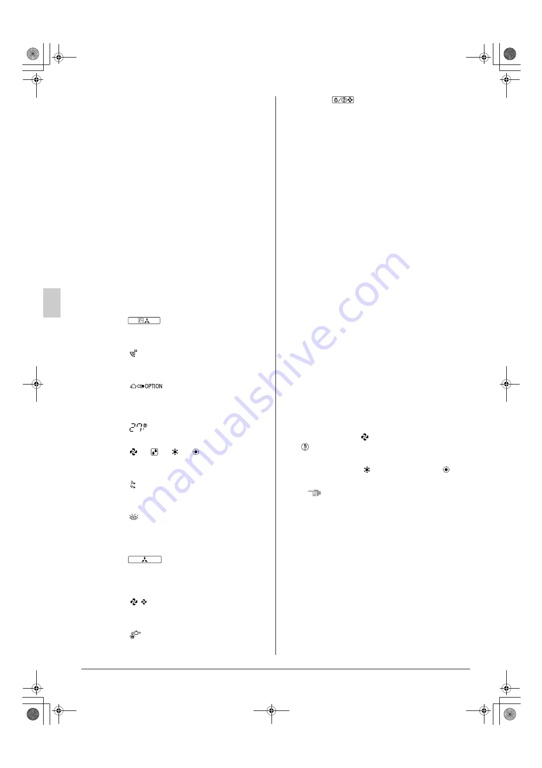
Names and functions of parts (Refer to figure 1)

1. Outdoor unit
2. Indoor unit
3. Remote controller
4. Inlet air
5. Outlet air
6. Cool/heat changeover remote control switch

(figure 1 shows systems with changeover remote
control switches)

3. REMOTE CONTROLLER AND

CHANGEOVER SWITCH: NAME
AND FUNCTION OF EACH
SWITCH AND DISPLAY
(Refer to figure 2 and 3)

1. On/off button

Press the button and the system will start. Press
the button again and the system will stop.

2. Operation lamp (red)

The lamp lights up during operation.

3. Display

(changeover under control)

It is impossible to changeover heat/cool with the
remote controller when this icon is displayed.

4. Display

(air flow flap)

Refer to the chapter “Operation procedure -
Adjusting the air flow direction”.

5. Display

(ventilation/air cleaning)

This display shows that the total heat exchange
and the air cleaning unit are in operation. (these
are optional accessories)

6. Display

(set temperature)

This display shows the temperature you have set.

7. Display

” “

” “

” “

(operation

mode)

This display shows the current operation mode.

8. Display

(programmed time)

This display shows the programmed time of the
system start or stop.

9. Display

(inspection/test operation)

When the inspection/test operation button is
pressed, the display shows the mode in which
the system actually is.

10. Display

(under centralized control)

When this display shows, the system is under
centralized control. (This is not a standard spec-
ification.)

11. Display

(fan speed)

This display shows the fan speed you have
selected.

12. Display

(time to clean air filter)

Refer to the indoor unit manual.

13. Display

(defrost/hot start)

Refer to the chapter “Operation procedure -
Explanation of heating operation.”

14. Timer mode start/stop button

Refer to the chapter “Operation procedure -
Programming start and stop of the system with
timer.”

15. Timer on/off button

Refer to the chapter “Operation procedure -
Programming start and stop of the system with
timer.”

16. Inspection/test operation button

This button is only used by qualified service
persons for maintenance purposes.

17. Programming time button

Use this button for programming start and/or stop
time.

18. Temperature setting button

Use this button for setting the desired temperature.

19. Filter sign reset button

Refer to the indoor unit manual.

20. Fan speed control button

Press this button to select the fan speed of your
preference.

21. Operation mode selector button

Press this button to select the operation mode of
your preference.

22. Air flow direction adjust button

Refer to the chapter “Operation procedure -
Adjusting the air flow direction”.

23. Fan only/air conditioning selector switch

Set the switch to “

” for fan only operation or to

” for heating or cooling operation.

24. Cool/heat changeover switch

Set the switch to “

” for cooling or to “

” for

heating operation.

NOTE

• In contradistinction to actual operating situations,

the display on figure 1 shows all possible indica-
tions.

• If the filter sign lamp lights up, clean the air filter as

explained in the indoor unit manual. After cleaning
and reinstalling the air filter: press the filter sign
reset button on the remote controller. The filter
sign lamp on the display will go out.

• The remote controller BRC1A52

(for FXS, FXM, FXL, FXN) does not have the dis-
play air flow flap (4) nor the air flow direction
adjust button (22).

C

TEST

01_3P114261-3M_EN.fm Page 3 Thursday, November 6, 2003 7:23 PM

Summary of Contents for RXY10MTL

Page 1: ...RXY36MY1 E RXY38MY1 E RXY40MY1 E RXY42MY1 E RXY44MY1 E RXY46MY1 E RXY48MY1 E RXY5MYL E RXY8MYL E RXY10MYL E RXY12MYL E RXY14MYL E RXY16MYL E RXY18MYL E RXY20MYL E RXY22MYL E RXY24MYL E RXY26MYL E RXY28MYL E RXY30MYL E RXY32MYL E RXY34MYL E RXY36MYL E RXY38MYL E RXY40MYL E RXY42MYL E RXY44MYL E RXY46MYL E RXY48MYL E RXY5MTL E RXY8MTL E RXY10MTL E RXY12MTL E RXY14MTL E RXY16MTL E RXY18MTL E RXY20MTL...

Page 2: ...to obrigado por ter adquirido este aparelho de ar condicionado Daikin Antes de utilizar o aparelho leia atentamente o presente manual de funcionamento Nele obterá informações sobre o modo de uti lizar correctamente o aparelho e ajuda na eventualidade de ocorrência de proble mas Depois de ler o manual guarde o para consultas futuras Спасибо за поêóпêó данноãо êондиционера фирмы Daikin До начала раб...

Page 3: ...2 1 RXY 4 2 3 5 4 00_3P114261 3M_CV fm Page 3 Friday November 7 2003 6 37 PM ...

Page 4: ...7 3 7 2 5 7 1 6 6 8 00_3P114261 3M_CV fm Page 4 Friday November 7 2003 6 37 PM ...

Page 5: ...9 10 14 11 10 Double flow Ceiling Suspended Wall Mounted Multi flow Corner 12 13 00_3P114261 3M_CV fm Page 5 Friday November 7 2003 6 37 PM ...

Page 6: ...normality such as smell of fire turn off power and call your dealer for instructions Ask your dealer for installation of the air con ditioner Incomplete installation performed by yourself may result in a water leakage electric shock and fire Ask your dealer for improvement repair and maintenance Incomplete improvement repair and maintenance may result in a water leakage electric shock and fire Do ...

Page 7: ...und the out door unit If they touch the unit carelessly it may result in injury Do not place a flower vase and anything con taining water Water may enter the unit causing an electric shock or fire Do not place the controller exposed to direct sunlight The LCD display may get discolored failing to dis play the data Do not wipe the controller operation panel with benzine thinner chemical dustcloth e...

Page 8: ...l 13 Display defrost hot start Refer to the chapter Operation procedure Explanation of heating operation 14 Timer mode start stop button Refer to the chapter Operation procedure Programming start and stop of the system with timer 15 Timer on off button Refer to the chapter Operation procedure Programming start and stop of the system with timer 16 Inspection test operation button This button is onl...

Page 9: ...ation To avoid condensation and water dripping out the unit If the temperature or the humidity is beyond these conditions safety devices may work and the air con ditioner may not operate 6 OPERATION PROCEDURE Operation procedure varies according to the com bination of outdoor unit and remote controller Read the chapter What to do before operation To protect the unit turn on the main power switch 6...

Page 10: ...ller shows 6 2 PROGRAM DRY OPERATION The function of this program is to decrease the humidity in your room with a minimum temperature decrease The micro computer automatically deter mines temperature and fan speed The system does not go into operation if the room temperature is low FOR SYSTEMS WITHOUT COOL HEAT CHANGEOVER REMOTE CONTROL SWITCH Refer to figure 5 Press the operation mode selector bu...

Page 11: ... The display flashes For setting the timer stop For setting the timer start Press the programming time button and set the time for stopping or starting the system Each time this button is pressed the time advances or goes backward by 1 hour Press the timer on off button The timer setting procedure ends The display or changes from flashing light to constant light NOTE When setting the timer off and...

Page 12: ...ling operation by using curtains or blinds Ventilate often Extended use requires special attention to venti lation Keep doors and windows closed If the doors and windows remain open air will flow out of your room causing a decrease in the cooling or heating effect Never place objects near the air inlet or the air outlet of the unit It may cause deterioration in the effect or stop the operation Tur...

Page 13: ...fied service person Immediately after the cooling operation stops and if the room temperature and humidity are low This is because warm refrigerant gas flows back into the indoor unit and generates steam Indoor unit outdoor unit When the system is changed over to heating operation after defrost operation Moisture generated by defrost becomes steam and is exhausted 8 7 NOISE OF AIR CONDITIONERS Ind...

Page 14: ...r and report the malfunction code If the system does not properly operate except for the above mentioned cases and none of the above mentioned malfunctions is evident inves tigate the system according to the following pro cedures 1 If the system does not operate at all Check if there is no power failure Wait until power is restored If power failure occurs during operation the system automati cally...

Page 15: ...3P114261 3M EM03A053A 0401 HT 00_3P114261 3M_CV fm Page 6 Friday November 7 2003 6 37 PM ...

Reviews: