RX(Y)Q5-10-1 RXQ RXYQ
RXYHQ1 RX(Y)Q14~18P7W1BA
VRVIII System air conditioner
4PW48461-1
Installation manual
6
■
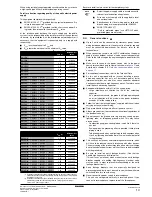
The pipe thickness of the refrigerant piping should comply
with relevant local and national regulations. The minimal pipe
thickness for R410A piping must be in accordance with the
table below.
3.
Make sure to use the particular branches of piping that have
been selected referring to chapter
"6.6. Example of connection"
on page 9
.
4.
In case the required pipe sizes (inch sizes) are not available, it is
also allowed to use other diameters (mm sizes), taken the
following into account:
■
select the pipe size nearest to the required size.
■
use the suitable adapters for the change-over from inch to
mm pipes (field supply).
5.
Precautions when selecting branch piping
When the equivalent pipe length between outdoor and indoor
units is 90 m or more, the size of the main pipes (both gas side
and liquid side) must be increased.
Depending on the length of the piping, the capacity may drop,
but even in such a case it is possible to increase the size of the
main pipes. Refer to
page 10
. If the recommended pipe size is
not available, stick to the original pipe diameter (which may
result in a small capacity decrease).
6.3.
Pipe connection
Be sure to perform a nitrogen blow when brazing and to read the
paragraph
"Caution to be taken when brazing refrigerant piping" on
page 5
first.
6.4.
Connecting the refrigerant piping
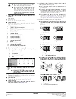
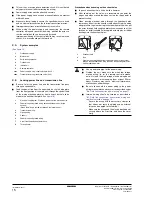
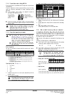
1
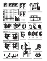
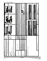
Front connection or side connection
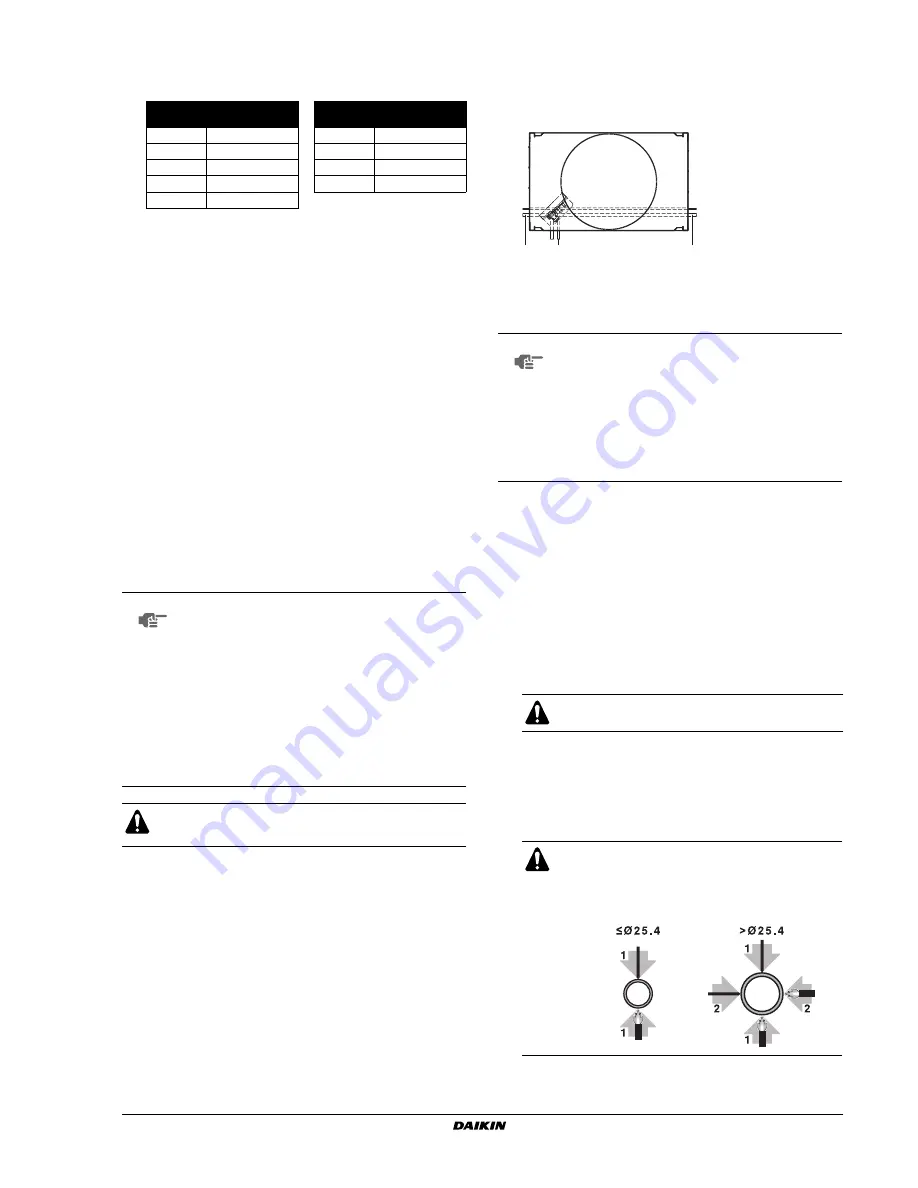
Installation of refrigerant piping is possible as front connection or
side connection (when taken out from the bottom) as shown in
the figure.
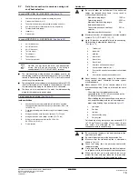
2
Removing the pinched piping
When connecting refrigerant piping to the outdoor unit, first
remove the pinched piping. Do not vent gases into the
atmosphere.
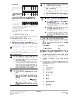
Removing of the pinched piping must be carried out according to
the following procedure:
1.
Make sure the stop valves are closed.
2.
Connect a charge hose to the service ports of all stop
valves.
3.
Recover the gas from the pinched piping.
4.
When all the gas is recovered from the pinched piping,
dissolve the brazing using a burner and remove the
pinched piping.
See
figure 6
.
Pipe Ø
Minimal thickness
t (mm)
Pipe Ø
Minimal thickness
t (mm)
6.4
0.80
22.2
0.80
9.5
0.80
28.6
0.99
12.7
0.80
34.9
1.21
15.9
0.99
41.3
1.43
19.1
0.80
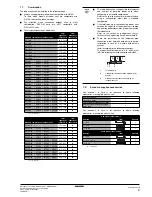
NOTE
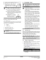
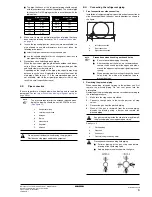
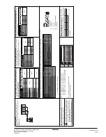
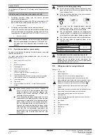
The pressure regulator for the nitrogen released when
doing the brazing should be set to 0.02 MPa or less.
(See figure 10)
Do not use anti-oxidants when brazing the pipe joints.
Residue can clog pipes and break equipment.
1
Refrigerant piping
2
Location to be brazed
3
Nitrogen
4
Taping
5
Manual valve
6
Regulator
7
Nitrogen
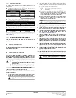
1
Left-side connection
2
Front connection
3
Right-side connection
NOTE
Precautions when knocking out knock holes
■
Be sure to avoid damaging the casing
■
After knocking out the holes, we recommend you
remove the burrs and paint the edges and areas
around the edges using the repair paint to prevent
rusting.
■
When passing electrical wiring through the knock
holes, wrap the wiring with protective tape to
prevent damage.
Any gas remaining inside the stop valve may blow off
the pinched piping, causing damage or injury.
1
Pinched piping
2
Stop valve
3
Service port
4
Point of melting the brazing metal
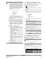
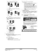
Precautions when connecting field piping.
■
Perform brazing at the gas stop valve before
brazing at the liquid stop valve.
■
Add brazing material as shown in the figure.
1
2
3
Summary of Contents for RXYHQ12P8W1B
Page 36: ...NOTES NOTES...
Page 38: ...4PW48461 1 Copyright Daikin...


