
Installation manual
7
RX(Y)Q5-10-1 RXQ RXYQ
RXYHQ1 RX(Y)Q14~18P7W1BA
VRVIII System air conditioner
4PW48461-1
3
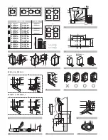
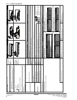
One outdoor unit installed: In case of RX(Y)Q5~18 +
RXYHQ12
(See figure 8)
■
Front connection:
Remove the stop valve cover to connect.
■
Bottom connection:
Remove the knock holes on the bottom frame and route the
piping under the bottom frame.
■
Processing the gas side accessory pipe (2)
Only in case of connecting at lateral side, cut the gas side
accessory pipe (2) as shown in
figure 11
.
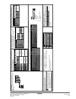
4
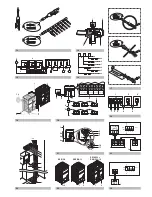
Outdoor units installed in a multiple outdoor unit system:
RXYQ20~54 + RXYHQ16~36
■
Front connection:
Remove the stop valve cover to connect.
(See figure 8)
■
Bottom connection:
Remove the knock holes on the bottom frame and route the
piping under the bottom frame.
(See figure 8)
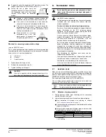
4.1 Precautions when connecting piping between outdoor
units (multiple outdoor unit system)
■
The 5 Hp unit type can not be used as an independent unit in
a multi system.
■
To connect the piping between outdoor units, an optional
multi connection piping kit BHFQ22P1007/1517 is always
required. When installing the piping, follow the instructions in
the installation manual that comes with the kit.
■
Only proceed with piping work after considering the
limitations on installing listed here and in the chapter
"6.4. Connecting the refrigerant piping" on page 6
, always
referring to the installation manual delivered with the kit.
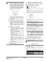
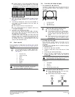
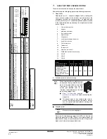
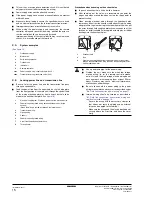
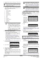
4.2 Possible installation patterns and configurations
■
The piping between the outdoor units must be routed level or
slightly upward to avoid the risk of oil retention into the piping
side.
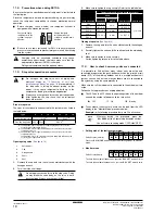
Pattern 1
Pattern 2
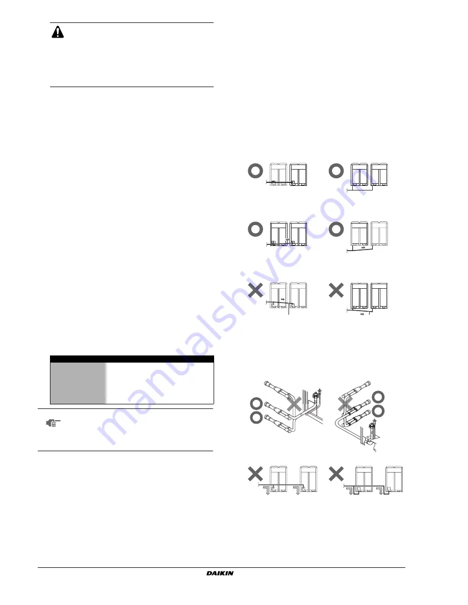
Prohibited patterns: change to pattern 1 or 2.
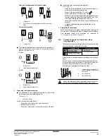
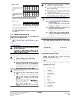
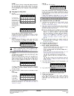
■
To avoid the risk of oil retention to the outmost outdoor unit,
always connect the stop valve and the piping between
outdoor units as shown in the 4 correct possibilities of the
figure below.
Prohibited patterns: change to pattern 1 or 2.
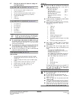
■
Be sure to use the supplied accessory pipes
when carrying out piping work in the field.
■
Be sure that the field installed piping does not
touch other pipes, the bottom panel or side
panel. Especially for the bottom and side
connection, be sure to protect the piping with
suitable insulation, to prevent it from coming into
contact with the casing.
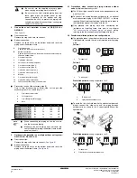
A
Front connection
Remove the stop valve cover to connect.
B
Bottom connection:
Remove the knock holes on the bottom frame and route the piping
under the bottom frame
1
Gas pipe stop valve
2
Liquid pipe stop valve
3
Service port for adding refrigerant
4
Gas side accessory pipe (1)
5
Gas side accessory pipe (2)
6
Liquid side accessory pipe (1)
7
Liquid side accessory pipe (2)
8
Brazing
9
Gas side piping (field supply)
10
Liquid side piping (field supply)
11
Punch the knockout holes (use a hammer)
1
Gas side accessory pipe
2
Cutting location
3
Gas side piping (field supply)
4
Base
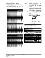
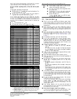
Model
A
B
C
D
RX(Y)Q5
(mm)
166
16
199
246
RX(Y)Q8
(mm)
156
17
188
247
RX(Y)Q10
(mm)
156
23
192
247
RX(Y)Q12
(mm)
150
29
192
247
RX(Y)Q14~18 +
RXYHQ12
(mm)
150
29
192
251
NOTE
■
When connecting the piping on site, be sure to
use the accessory piping.
■
Make sure the onsite piping does not come into
contact with other piping, the bottom frame or side
panels of the unit.
1
1
1
To indoor unit
1
1
1
To indoor unit
1
1
2
2
1
To indoor unit
2
Piping between outdoor units
1
1
2
2
2
2
1
To indoor unit
2
Oil collects to the outmost outdoor unit.
Summary of Contents for RXYHQ12P8W1B
Page 36: ...NOTES NOTES...
Page 38: ...4PW48461 1 Copyright Daikin...


