Installation manual
13
RX(Y)Q5-10-1 RXQ RXYQ
RXYHQ1 RX(Y)Q14~18P7W1BA
VRVIII System air conditioner
4PW48461-1
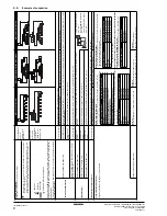
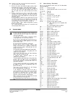
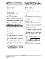
L1,L2,L3 .............. Live
N ......................... Neutral
............ Field wiring
............... Terminal strip
....................... Connector
...................... Terminal
....................... Protective earth (screw)
BLK ..................... Black
BLU ..................... Blue
BRN .................... Brown
GRN .................... Green
GRY .................... Grey
ORG .................... Orange
PNK..................... Pink
RED .................... Red
WHT .................... White
YLW .................... Yellow
8.2.
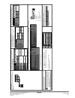
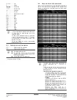
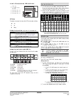
Optional parts cool/heat selector
S1S ..................... Selector switch (fan, cool/heat)
S2S ..................... Selector switch (cool/heat)
* = Only for unit of class 10~18 hp
8.3.
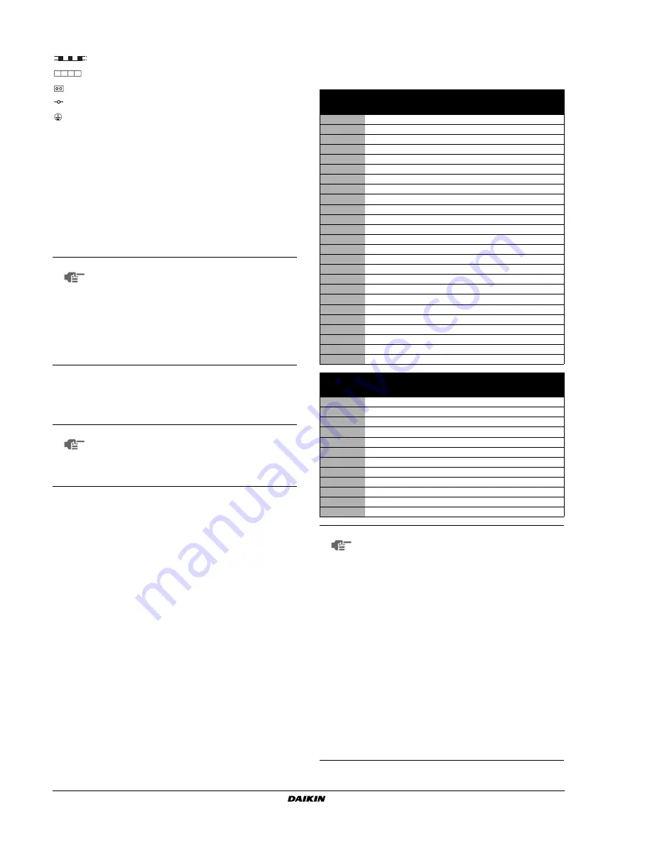
Power circuit and cable requirements
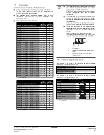
A power circuit (see table below) must be provided for connection of
the unit. This circuit must be protected with the required safety
devices, i.e. a main switch, a slow blow fuse on each phase and an
earth leakage breaker.
NOTE
(1) This wiring diagram only applies to the outdoor unit.
(4) When using the option adaptor, refer to the
installation manual.
(5) Refer to the installation manual, for connection
wiring to indoor-outdoor transmission F1-F2, outdoor-
multi transmission Q1-Q2 and on how to use BS1~BS5
and DS1, DS2 switch.
(6) Do not operate the unit by short-circuiting
protection device S1PH.
NOTE
■
Use copper conductors only.
■
For connection wiring to the central remote
controller, refer to the installation manual of the
central remote controller.
■
Use insulated wire for the power cord.
Phase and
frequency
Voltage
Minimum
circuit
ampere
Recommended
fuses
Transmission line
section
RX(Y)Q5
3 N~50 Hz
400 V
11.9 A
16 A
0.75~1.25 mm
2
RX(Y)Q8
3 N~50 Hz
400 V
18.5 A
25 A
0.75~1.25 mm
2
RX(Y)Q10
3 N~50 Hz
400 V
21.6 A
25 A
0.75~1.25 mm
2
RX(Y)Q12
3 N~50 Hz
400 V
22.7 A
25 A
0.75~1.25 mm
2
RX(Y)Q14
3 N~50 Hz
400 V
31.5 A
40 A
0.75~1.25 mm
2
RX(Y)Q16
3 N~50 Hz
400 V
31.5 A
40 A
0.75~1.25 mm
2
RX(Y)Q18
3 N~50 Hz
400 V
32.5 A
40 A
0.75~1.25 mm
2
RXYQ20
3 N~50 Hz
400 V
41.2 A
50 A
0.75~1.25 mm
2
RXYQ22
3 N~50 Hz
400 V
44.3 A
50 A
0.75~1.25 mm
2
RXYQ24
3 N~50 Hz
400 V
50.4 A
50 A
0.75~1.25 mm
2
RXYQ26
3 N~50 Hz
400 V
51.0 A
63 A
0.75~1.25 mm
2
RXYQ28
3 N~50 Hz
400 V
54.1 A
63 A
0.75~1.25 mm
2
RXYQ30
3 N~50 Hz
400 V
55.2 A
63 A
0.75~1.25 mm
2
RXYQ32
3 N~50 Hz
400 V
63.0 A
80 A
0.75~1.25 mm
2
RXYQ34
3 N~50 Hz
400 V
64.0 A
80 A
0.75~1.25 mm
2
RXYQ36
3 N~50 Hz
400 V
65.0 A
80 A
0.75~1.25 mm
2
RXYQ38
3 N~50 Hz
400 V
73.7 A
100 A
0.75~1.25 mm
2
RXYQ40
3 N~50 Hz
400 V
81.5 A
100 A
0.75~1.25 mm
2
RXYQ42
3 N~50 Hz
400 V
82.5 A
100 A
0.75~1.25 mm
2
RXYQ44
3 N~50 Hz
400 V
83.5 A
100 A
0.75~1.25 mm
2
RXYQ46
3 N~50 Hz
400 V
86.6 A
100 A
0.75~1.25 mm
2
RXYQ48
3 N~50 Hz
400 V
87.7 A
100 A
0.75~1.25 mm
2
RXYQ50
3 N~50 Hz
400 V
96.5 A
125 A
0.75~1.25 mm
2
RXYQ52
3 N~50 Hz
400 V
96.5 A
125 A
0.75~1.25 mm
2
RXYQ54
3 N~50 Hz
400 V
97.5 A
125 A
0.75~1.25 mm
2
Phase and
frequency
Voltage
Minimum
circuit
ampere
Recommended
fuses
Transmission line
section
RXYHQ12
3 N~50 Hz
400 V
22.5 A
25 A
0.75~1.25 mm
2
RXYHQ16
3 N~50 Hz
400 V
37.0 A
50 A
0.75~1.25 mm
2
RXYHQ18
3 N~50 Hz
400 V
40.1 A
50 A
0.75~1.25 mm
2
RXYHQ20
3 N~50 Hz
400 V
41.2 A
50 A
0.75~1.25 mm
2
RXYHQ22
3 N~50 Hz
400 V
44.3 A
50 A
0.75~1.25 mm
2
RXYHQ24
3 N~50 Hz
400 V
55.5 A
63 A
0.75~1.25 mm
2
RXYHQ26
3 N~50 Hz
400 V
58.6 A
80 A
0.75~1.25 mm
2
RXYHQ28
3 N~50 Hz
400 V
61.7 A
80 A
0.75~1.25 mm
2
RXYHQ30
3 N~50 Hz
400 V
62.8 A
80 A
0.75~1.25 mm
2
RXYHQ32
3 N~50 Hz
400 V
63.9 A
80 A
0.75~1.25 mm
2
RXYHQ34
3 N~50 Hz
400 V
67.0 A
80 A
0.75~1.25 mm
2
RXYHQ36
3 N~50 Hz
400 V
68.1 A
80 A
0.75~1.25 mm
2
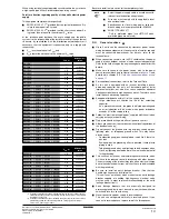
NOTE
The above table indicates power specifications for
standard combinations. See
"1. Introduction" on
page 1
.
If using anything other than the above combinations in
a multiple outdoor unit system, calculate using the
following procedure.
Calculate the recommended fuse capacity
Calculate, by adding the minimum circuit ampere
of each used unit (according to the table above),
multiply the result by 1.1 and select the next
higher recommended fuse capacity.
Example
Combining the RXYQ30 by using the RXYQ8,
RXYQ10, and RXYQ12.
Minimum circuit ampere of the RXYQ8 = 18.5 A
Minimum circuit ampere of the RXYQ10 = 21.6 A
Minimum circuit ampere of the RXYQ12 = 22.7 A
Accordingly, the minimum circuit ampere of the
RXYQ30=18.5+21.6+22.7= 62.8 A
Multiplying the above result by 1.1
(62.8 x 1.1)=69.08 A, so the recommended fuse
capacity would be 80 A.
Summary of Contents for RXYHQ12P8W1B
Page 36: ...NOTES NOTES...
Page 38: ...4PW48461 1 Copyright Daikin...

