RX(Y)Q5-10-1 RXQ RXYQ
RXYHQ1 RX(Y)Q14~18P7W1BA
VRVIII System air conditioner
4PW48461-1
Installation manual
20
11.5. Additional refrigerant charge
There are two ways to charge refrigerant. Use the selected method
following the described procedure below.
■
Adding refrigerant using leak detection function.
Refer to
"1 Adding refrigerant using leak detection function" on
page 20
■
Adding refrigerant without using leak detection function.
Refer to
"2 Adding refrigerant without using leak detection
function" on page 22
Follow the procedures below.
1
Adding refrigerant using leak detection function
The automatic refrigerant charging has limits as described
below.
At out of limit, the system can not operate the automatic
refrigerant charging.
To speed up the proces of charging refrigerant for large systems, it is
recommended to first manually charge a portion of the refrigerant
first before performing automatic charging.
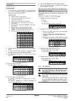
1
Calculate how much refrigerant to be added using the formula
explained in the chapter
"How to calculate the additional
refrigerant to be charged" on page 10
.
2
The amount of pre-charging is 10 kg less than the calculated
amount.
3
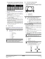
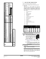
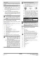
Open valve C (valves A and B and the stop valves must be left
closed) and charge the refrigerant in liquid form via the liquid
side stop valve service port.
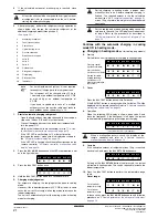
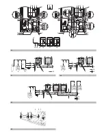
(See figure 28)
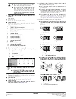
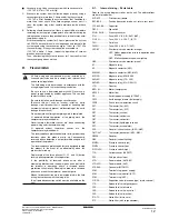
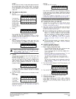
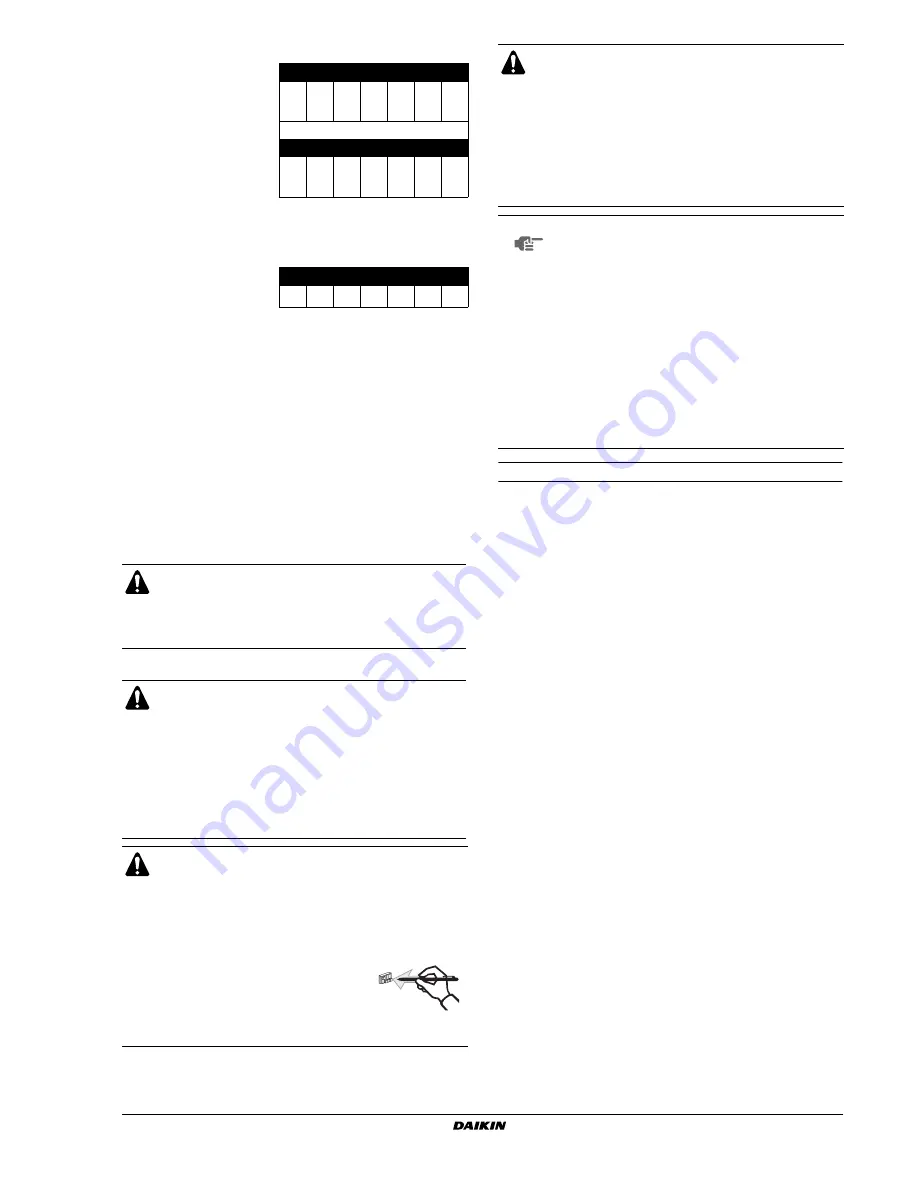
3
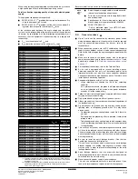
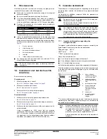
Monitor mode
H1P
H2P
H3P
H4P
H5P
H6P
H7P
Selection status of how many
connected indoor units to
display.
c x
x
x w x w
OR
H1P
H2P
H3P
H4P
H5P
H6P
H7P
Selection status of how many
connected outdoor units to
display.
c x
x w x
x
x
Pressing the
button causes the LED display to show the
data on the number of indoor units that are connected or how many
outdoor units that are connected in a multiple outdoor unit system.
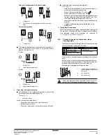
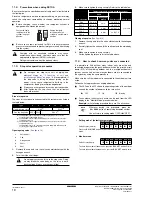
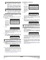
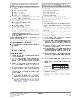
4
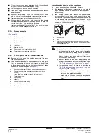
Monitor mode
H1P
H2P
H3P
H4P
H5P
H6P
H7P
Displaying the number of
connected indoor units
c x c x c c x
32
16
8
4
2
1
Calculate the number of connected indoor units by adding the values of
all (H2P~H7P) blinking (
c
) LEDs together.
In this example: 16+4+2=22 units
Press the
button to return to step 1, setting mode 1
(H1P=
x
"OFF").
Adding refrigerant using the automatic refrigerant charging
function is recommended.
If refrigerant is added manually, without using the
automatic refrigerant charging function, the refrigerant leak
detection function can not be used.
■
When charging a system, charging over the
permissible quantity can cause liquid hammer.
■
Always use protective gloves and protect your eyes
when charging refrigerant.
■
When the refrigerant charging procedure is done or
when pausing, close the valve of the refrigerant tank
immediately. If the tank is left with the valve open, the
amount of refrigerant which is properly charged may
get off point. More refrigerant may be charged by any
remaining pressure after the unit has stopped.
Electric shock warning
■
Close the electric box lid before turning on the main
power.
■
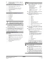
Perform the settings on the circuit board (A1P) of the
outdoor unit and check the LED display after the
power is on via the service lid which is in the lid of the
electric box.
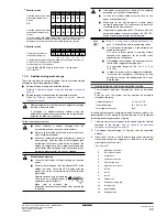
Operate switches with an insulated
stick (such as a ball-point pen) to
avoid touching the life parts.
Make sure to re-attach the
inspection cover into the switch box cover after the job
is finished.
BS3 RETURN
BS1 MODE
■
If the power of some units is turned off, the charging
procedure can not be finished properly.
■
In case of a multiple outdoor system, turn on the
power of all outdoor units.
■
Make sure to turn ON the power 6 hours before
starting the operation. This is necessary to warm the
crankcase by the electric heater.
■
If operation is performed within 12 minutes after the
indoor and outdoor units are turned on, the H2P-LED
will be lit and the compressor will not operate.
NOTE
■
See
"11.3. Stop valve operation procedure" on
page 19
for details on how to handle stop valves.
■
The refrigerant charging port is connected to the
piping inside the unit.
The unit’s internal piping is already factory
charged with refrigerant, so be careful when
connecting the charge hose.
■
After adding the refrigerant, do not forget to close
the lid of the refrigerant charging port.
The tightening torque for the lid is 11.5 to
13.9 N•m.
■
In order to ensure uniform refrigerant distribution,
it may take the compressor ±10 minutes to start
up after the unit has started operation. This is not
a malfunction.
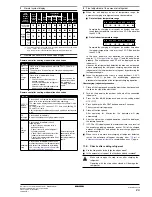
Outdoor temperature
: 0°C DB~43°C DB
Indoor temperature
: 20°C DB~32°C DB
Total indoor unit capacity
:
≥
80%
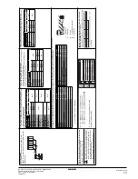
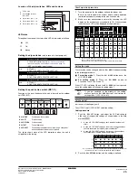
1
Measuring instrument
2
Tank (siphon system)
3
Charge hose
4
Liquid line stop valve
5
Gas line stop valve
6
Stop valve service port
7
Valve B
8
Valve C
9
Valve A
10
Outdoor unit
11
Refrigerant charge port
12
To indoor unit
13
Interunit piping
14
Refrigerant flow
Summary of Contents for RXYHQ12P8W1B
Page 36: ...NOTES NOTES...
Page 38: ...4PW48461 1 Copyright Daikin...

