background image

RX(Y)Q5-10-1 RXQ RXYQ
RXYHQ1 RX(Y)Q14~18P7W1BA
VRVIII System air conditioner
4PW48461-1

Installation manual

24

3

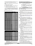
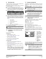
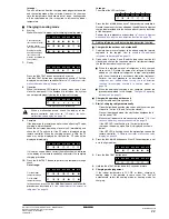
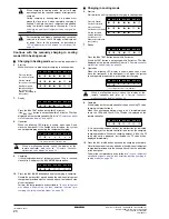
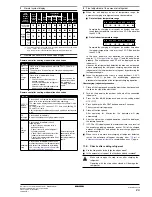
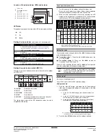
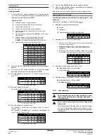
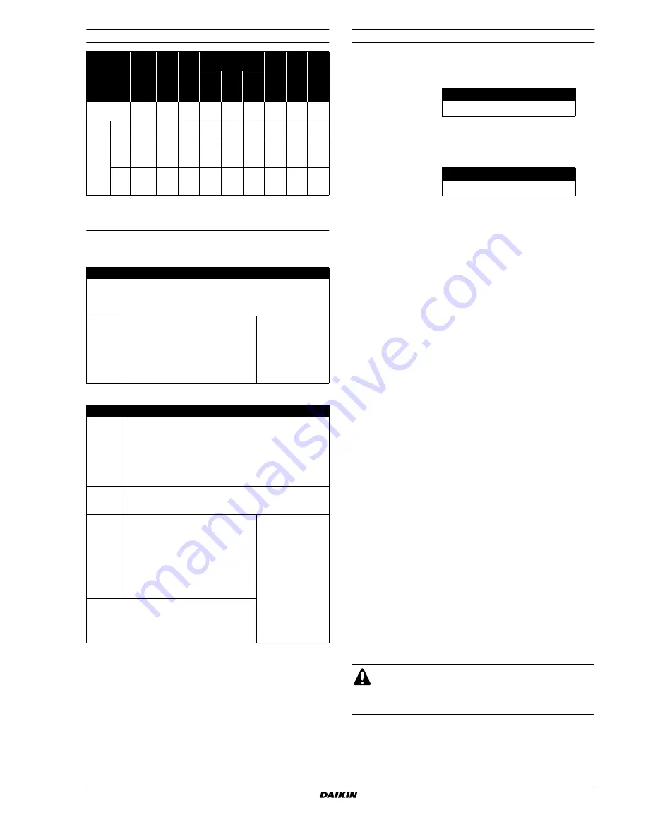
Normal system display

4

Remote controller malfunction code display

Remote controller heating mode malfunction codes

Remote controller cooling mode malfunction codes

5

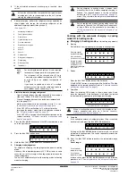
Final adjustment of the amount of refrigerant

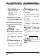
When the unit displays an out of temperature range, the
automatic charging of refrigerant can not be completed.

Out of outdoor temperature range

Complete the charging of refrigerant on another time when
the outdoor temperature is warmer than 0°C DB and colder
than 43°C DB.

Out of indoor temperature range

Complete the charging of refrigerant on another time when
the indoor temperature is warmer than 20°C DB and colder
than 32°C DB.

In this case, perform a test operation (as explained in the
chapter 

"12.4. Test operation" on page 27

) and the unit will work

properly. (The malfunction code 

U3

  will be displayed on the

indoor unit.)
However, the refrigerant leak detection function can not be used
before completing the refrigerant charging operation and the
judgement of the initial amount of refrigerant by performing the
test operation again.

When the temperature has come in range (outdoor = 0~43°C,
indoor 

20~32°C), perform the overcharging judgement

procedure for completion of the refrigerant charging operation.

Overcharging judgement procedure

1

Close all the front panels except the electric box front panel and
the lid on the side of the electric box.

2

Turn  on the power to the outdoor unit and all the connected
indoor units.

3

Press the 

 button once and set the setting model

H1P = OFF.

4

Press and hold the 

 button down for 5 seconds.

The system will start operating.

5

Close all the front panels.

After operating for 40 

minutes, the operation will stop

automatically.

6

After the system has stopped operating, check the display on
the remote controller.

7

If 

E3

F6

 or 

UF

 is displayed on the remote controller as a result of

the overcharge judging operation, recover 20% of the charged
amount of refrigerant and perform the overcharge judgement
procedure again.

When there is no more overcharging of refrigerant detected,
restart the automatic refrigerant charging from 

"1. Start  of

automatic charging refrigerant"

 as explained on 

page 21

 again.

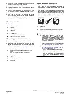
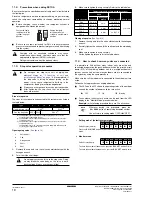
11.6. Checks after adding refrigerant

Are the stop valves for both liquid and gas open?

Is the amount of refrigerant, that has been added, recorded?

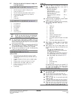
LED 

display

(Default 

status

before 

delivery)

Micro-

computer
operation

monitor

Mode

Ready

/Error

Cooling/Heating 

changeover

Low 

noise

Demand

Multi

Indivi-

dual

Bulk 

(master)

Bulk 

(slave)

HAP

H1P

H2P

H3P

H4P

H5P

H6P

H7P

H8P

Single outdoor 

unit system

c

x

x

w

x

x

x

x

x

Multiple 
outdoor 

unit 

system

Master 

unit

(a)

(a) The state of the H8P (multi) LED in a multi-system shows wich unit is the master 

unit (

w

), slave 1 unit (

c

) or slave 2 unit (

x

). 

Only the master unit is connected to the indoor units with interunit wiring.

c

x

x

w

x

x

x

x

w

Slave 

unit 
1

(a)

c

x

x

x

x

x

x

x

c

Slave 

unit 
2

(a)

c

x

x

x

x

x

x

x

x

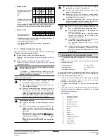
Error code 

P8 

recharge 
operation

Close valve A immediately and press the TEST OPERATION 
button once.
The operation will restart from the charging mode judgement 
onwards.

P2

charge 
hold

Close valve A immediately. Check 
following items:
- Check if the gas side stop valve is 

opened correctly

- Check if the valve of the refrigerant 

cylinder is opened

- Check if the air inlet and outlet of the 

indoor unit are not obstructed

After correcting the 
abnormality, restart 
the automatic 
charging procedure 
again.

Error code 

PA

PH

PC

replace 
cylinder

Close valve A and replace the empty cylinder. When renewed, 
open valve A (the outdoor unit will not stop operating).
The code on the display shows the unit where a cylinder is to be 
renewed:

PA

 = master unit, 

PH

 = slave unit 1, 

PC

 = slave unit 2, flashing 

PA

PH

 and 

PC

 = all units

After recplacing the cylinder, open valve A again and continue the 
work.

P8 

recharge 
operation

Close valve A immediately.
Restart the automatic charging procedure again.

P2

charge 
hold

Close valve A immediately. Check 
following items:
- Check if the gas side stop valve is 

opened correctly

- Check if the valve of the refrigerant 

cylinder is opened

- Check if the air inlet and outlet of the 

indoor unit are not obstructed

- Check if the indoor temperature is not 

lower than 20°C DB

After correcting the 
abnormality, restart 
the automatic 
charging procedure 
again.

*
abnormal 
stop

Close valve A immediately. Confirm the 
malfunction code by the remote controller 
and correct the abnormality by following 
the 

"Correcting after abnormal completion 

of the test operation" on page 29

.

H1P

H2P

H3P

H4P

H5P

H6P

H7P

w c c c w x

x

H1P

H2P

H3P

H4P

H5P

H6P

H7P

w c c c x w x

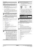
Make sure to open the stop valves after charging the
refrigerant.

Operating with the stop valves closed will damage the
compressor.

BS1  MODE

BS4  TEST

Summary of Contents for RXYHQ12P8W1B

Page 1: ...ION MANUAL RXQ5P7W1B RXQ8P7W1B RXQ10P7W1B RXQ12P7W1B RXQ14P7W1BA RXQ16P7W1BA RXQ18P7W1BA RXYQ5P7W1B RXYQ8P8W1B RXYQ10P7W1B RXYQ12P7W1B RXYHQ12P8W1B RXYQ14P7W1BA RXYQ16P7W1BA RXYQ18P7W1BA System air co...

Page 2: ...Q16 36 RX Y Q5 RX Y Q8 18 RXYHQ12 2 1 h1 h2 a 10 mm b 300 mm c 10 mm d 500 mm a 50 mm b 100 mm c 50 mm d 500 mm a 200 mm b 300 mm a 10 mm b 300 mm c 10 mm d 500 mm e 20 mm a 50 mm b 100 mm c 50 mm d 5...

Page 3: ...UNIT TO MULTI UNIT A1P 3 A B C F1 F2 F1 F2 Q1 Q2 Q1 Q2 A1P 4 4 5 6 2 1 3 Q1 Q2 7 5 3 4 1 6 6 2 2 TO IN D UNIT F1 F2 DS1 1 2 3 4 OFF ON O U T I N F1 F2 P1 P2 P1 P2 1 A B C A B C 1 DS1 1 2 3 4 OFF ON O...

Page 4: ...a 16 megfelelnek az al bbi szabv ny ok nak vagy egy b ir nyad dokumentum ok nak ha azokat el r s szerint haszn lj k 17 spe niaj wymogi nast puj cych norm i innych dokument w normalizacyjnych pod warun...

Page 5: ...yll stysl mp tila M C Kylm aine N Varmuuspainelaitteen asetus P bar Valmistusnumero ja valmistusvuosi katso mallin nimikilpi 14 Maxim ln p pustn tlak PS K bar Minim ln maxim ln p pustn teplota TS TSmi...

Page 6: ...ndoor units for air conditioning purposes and suitable for R410A The present installation manual describes the procedures for unpacking installing and connecting the RX Y Q P RXYHQ units Installation...

Page 7: ...Q54 RXYQ18 RXYQ18 RXYQ18 675 1755 64 Standard combination of outdoor units Total capacity of indoor units Total quantity of indoor units RXYHQ12 a a main unit 150 390 30 RXYHQ16 RXYQ8 RXYQ8 200 520 32...

Page 8: ...ave obstacles the wall heights have no influence on any indicated service space dimensions 3 Make sure that there is no danger of fire due to leakage of inflammable gas 4 Ensure that water can not cau...

Page 9: ...fore recommended to install the equipment and electric wires keeping proper distances away from stereo equipment personal computers etc See figure 2 In places with weak reception keep distances of 3 m...

Page 10: ...is to be installed on a frame install the waterproofing board within a distance of 150 mm under the unit in order to prevent infiltration of water coming from under the unit When installed in a corros...

Page 11: ...as shown in the figure 2 Removing the pinched piping When connecting refrigerant piping to the outdoor unit first remove the pinched piping Do not vent gases into the atmosphere Removing of the pinche...

Page 12: ...into the piping side Pattern 1 Pattern 2 Prohibited patterns change to pattern 1 or 2 To avoid the risk of oil retention to the outmost outdoor unit always connect the stop valve and the piping betwe...

Page 13: ...stallation may lead to malfunction of the outdoor unit 6 Piping length restrictions Make sure to perform the piping installation within the range of the maximum allowable pipe length allowable level d...

Page 14: ...kits can only be used with R410A How to select the refnet joint When using refnet joints at the first branch counted from the outdoor unit side Choose from the following table in accordance with the c...

Page 15: ...YQ34P 1x 16 1x 18 If the outdoor unit is RXYQ34P and the piping lengths are as below B A C D E B B Outdoor unit capacity type Piping size outer diameter mm Gas pipe Liquid pipe RX Y Q5 15 9 9 5 RX Y Q...

Page 16: ...ength of above pipes must be doubled except main pipe and the pipes that not increase the pipe size a b 2 c 2 d 2 e 2 f 2 g 2 h i j k l m n p 1000 m Indoor unit to the nearest branch kit 40 m h i j p...

Page 17: ...lator R10 Resistor current sensor A4P A8P R31T 33T Thermistor discharge M1C M3C R50 59 Resistor R95 Resistor current limiting S1NPH Pressure sensor high S1NPL Pressure sensor low S1PH 3PH Pressure swi...

Page 18: ...mm2 RXYQ30 3 N 50 Hz 400 V 55 2 A 63 A 0 75 1 25 mm2 RXYQ32 3 N 50 Hz 400 V 63 0 A 80 A 0 75 1 25 mm2 RXYQ34 3 N 50 Hz 400 V 64 0 A 80 A 0 75 1 25 mm2 RXYQ36 3 N 50 Hz 400 V 65 0 A 80 A 0 75 1 25 mm2...

Page 19: ...bnormal rise in electrical potential in the grounding This unit uses an inverter and therefore generates noise which will have to be reduced to avoid interfering with other devices The outer casing of...

Page 20: ...h protective tape in order to prevent damage to the wires put the wires through field supplied protective wire conduits at that location or install suitable field supplied wire nipples or rubber bushi...

Page 21: ...ow the limits below If the unit to unit cables are beyond these limits it may result in malfunction of transmission Maximum wiring length 1000 m Total wiring length 2000 m Maximum interunit wiring len...

Page 22: ...are established When disconnecting the power supply cord the current carrying connections must be separated before the earth connection is Length of the conductors between the power supply cord anchor...

Page 23: ...additional charging For charging the additional refrigerant follow the procedure as described in this chapter 11 1 Important information regarding the refrigerant used This product contains fluorinat...

Page 24: ...uid refrigerant with the cylinder in upright position Charge the liquid refrigerant with the cylinder in up side down position Charging with an unsuitable substance may cause explosions and accidents...

Page 25: ...ing function the refrigerant leak detection function can not be used When charging a system charging over the permissible quantity can cause liquid hammer Always use protective gloves and protect your...

Page 26: ...d press the button once As long as the button is not pressed the system will remain in heating mode This can be required to increase the indoor temperature 10 Press the button to perform the temperatu...

Page 27: ...nd B and the stop valves must be left closed and charge the required amount of refrigerant through the liquid side stop valve service port When the required amount of refrigerant is fully charged clos...

Page 28: ...hown above correct the malfunction as indicated in the display of the remote controller and restart the complete charging procedure When the charging amount is little the PE code may not be displayed...

Page 29: ...ing refrigerant Are the stop valves for both liquid and gas open Is the amount of refrigerant that has been added recorded LED display Default status before delivery Micro computer operation monitor M...

Page 30: ...sulated stick such as a ball point pen to avoid touching live parts Make sure to re attach the inspection cover 1 into the switch box cover 2 after the job is finished WARNING ELECTRIC SHOCK Caution w...

Page 31: ...n wiring and cool heat selection on page 16 not installed factory setting 2 4 NOT USED DO NOT CHANGE THE FACTORY SETTING What to set with dip switch DS2 1 4 NOT USED DO NOT CHANGE THE FACTORY SETTING...

Page 32: ...n level setting via the external control adapter F power consumption limitation setting via the external control adapter G enabling function of the low noise operation level setting and or power consu...

Page 33: ...f the operation is completed Normal operation will be possible after 5 minutes If a malfunction code is displayed on the remote controller correct the malfunction and perform the check operation again...

Page 34: ...gerant gas is not exceeded in the unlikely event of major leak in the system and this in accordance to the local applicable regulations and standards Maximum concentration level The maximum charge of...

Page 35: ...n level then it will be necessary to revise the system Please consult your supplier 15 DISPOSAL REQUIREMENTS Dismantling of the unit treatment of the refrigerant of oil and of other parts must be done...

Page 36: ...NOTES NOTES...

Page 37: ...3 2 9 6 6 6 6 7 4 11 8 6 6 6 6 6 6 7 7 9 8 4 11 6 6 1 10 3 2 6 6 6 6 27 13 6 9 8 1 2 4 3 5 14 15 16 12 11 10 10 7 28 13 14 3 5 4 2 1 7 8 9 6 10 10 11 10 2 2 12 9 9 29 30 13 14 3 5 4 2 1 7 8 9 6 10 10...

Page 38: ...4PW48461 1 Copyright Daikin...

Reviews: