General Functionality
ESIE04-01
2–6
Part 2 – Functional Description
3
1
2
4
5
1.3
Forced Operating Mode (Emergency Operation)
Purpose
The table below describes the purpose of the forced operating mode.
Starting conditions
You can operate the system manually by changing the emergency switch on the indoor and outdoor
PCB from "normal" to "emergency". When the system is operating in "emergency" it can not control
the room temperature.
Both the indoor and outdoor unit must be set to "emergency" while the power is off.
Ending conditions
You can end the emergency operation by changing the "emergency" switch back to "normal" while the
power is OFF.
Emergency
operation
Below table explains what will happen when the switch is set to "emergency":
How to set
Emergency
Operation
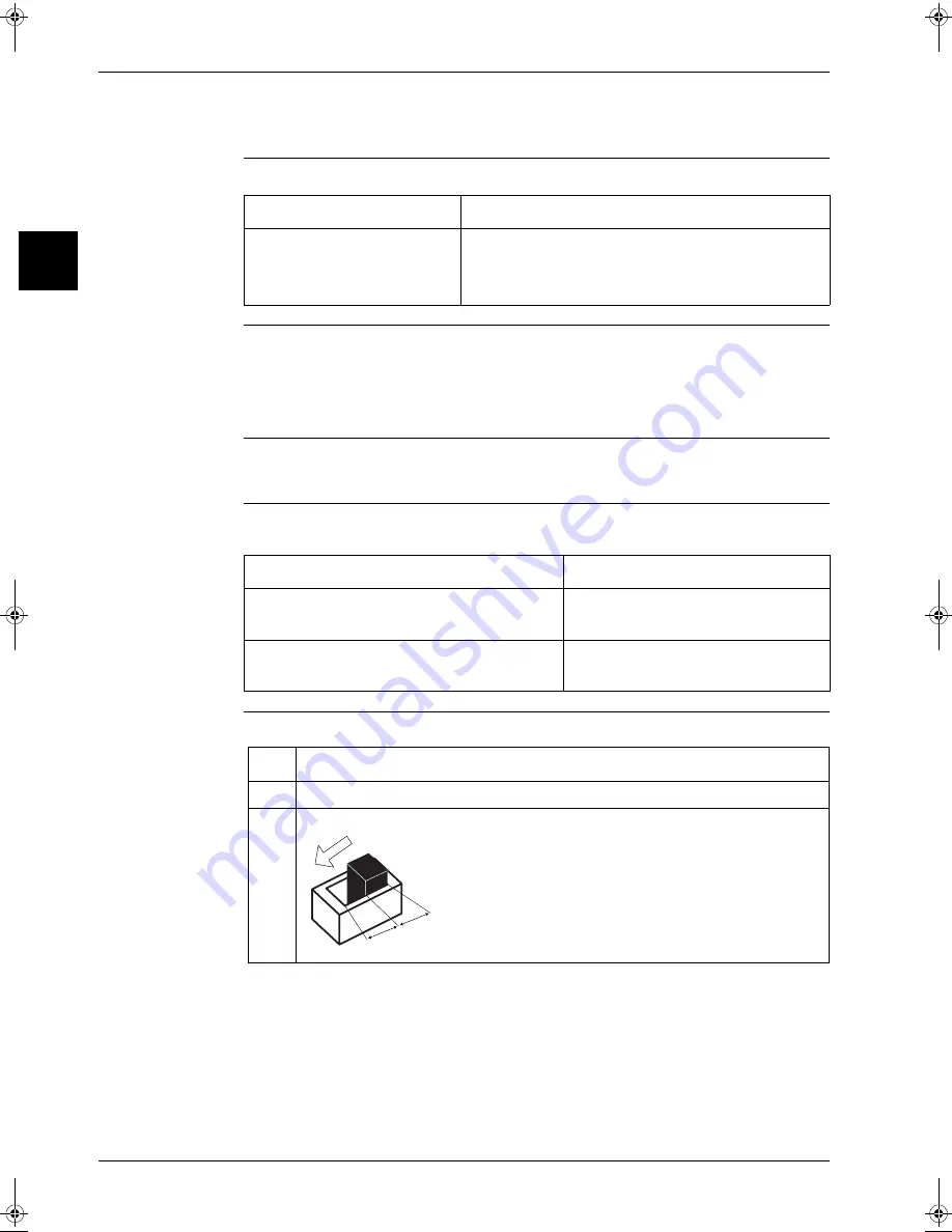
To set emergency operation, proceed as follows:
If...
Then...
P
R/C is defective
P
Indoor PCB is defective
P
Outdoor PCB is defective
Forced operating mode can be used to go to cooling or heat-
ing. In forced operating mode, the compressor is forced to
operate until the defective indoor or outdoor PCB is back
online.
Changing the switch to "emergency" for the…
Switches ON the…
Indoor unit
P
Indoor fan§
P
Drain pump
Outdoor unit
P
Compressor§
P
Outdoor fan(s)
Step
Action
1
Turn OFF the power.
2
Switch ON the emergency switch (SS1) on the indoor PCB.
Normal
Emergency
RZQ - Final.book Page 6 Wednesday, September 8, 2004 8:40 AM
Summary of Contents for RZQ71~125B7V3B
Page 1: ...Service Manual ESIE04 01 RZQ71 125B7V3B Sky Air Inverter R 410A B series ...
Page 2: ......
Page 24: ...ESIE04 01 1 2 Part 1 System Outline 3 1 1 5 ...
Page 32: ...General Outline Outdoor Units ESIE04 01 1 10 Part 1 System Outline 3 1 1 4 5 ...
Page 64: ...General Outline Indoor Units ESIE04 01 1 42 Part 1 System Outline 3 1 1 4 5 ...
Page 76: ...Specifications ESIE04 01 1 54 Part 1 System Outline 3 1 1 4 5 ...
Page 92: ...Functional Diagrams ESIE04 01 1 70 Part 1 System Outline 3 1 1 4 5 ...
Page 94: ...ESIE04 01 1 72 Part 1 System Outline ...
Page 122: ...Wiring Diagrams ESIE04 01 1 100 Part 1 System Outline 3 1 1 4 5 ...
Page 140: ...ESIE04 01 2 2 Part 2 Functional Description 3 1 2 5 ...
Page 162: ...General Functionality ESIE04 01 2 24 Part 2 Functional Description 3 1 2 4 5 ...
Page 200: ...Outdoor Unit Functional Concept ESIE04 01 2 62 Part 2 Functional Description 3 1 2 4 5 ...
Page 202: ...ESIE04 01 3 2 Part 3 Troubleshooting 3 1 3 5 ...
Page 288: ...Error Codes Outdoor Units ESIE04 01 3 88 Part 3 Troubleshooting 3 1 3 4 5 ...
Page 312: ...Additional Checks for Troubleshooting ESIE04 01 3 112 Part 3 Troubleshooting 3 1 3 4 5 ...
Page 314: ...ESIE04 01 4 2 Part 4 Commissioning and Test Run 3 1 4 5 ...
Page 356: ...ESIE04 01 5 2 Part 5 Disassembly and Maintenance 3 1 5 ...
Page 484: ...ESIE04 01 viii Index 3 1 4 5 ...


