General Functionality
ESIE04-01
2–14
Part 2 – Functional Description
3
1
2
4
5
1.10
Test run control
Purpose
When operating the RZQ units for the first time after installation, the unit will - depending on the
selected operation mode - perform a test run operation first.
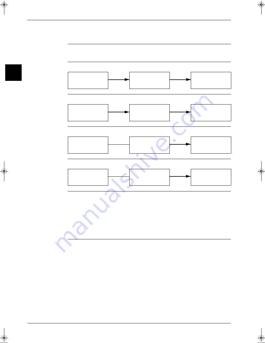
Situation 1
Cooling - first operation after installation in "Cooling mode"
Situation 2
Cooling - first operation after installation in "Test run mode"
Situation 3
Heating - first operation after installation in "Heating mode"
Situation 4
Heating - first operation after installation in "Test run mode"
Remarks
P
When running in test run mode, the unit will sense on site installation parameters (e.g.: failure to
open stop valves,..) and indicate the applicable malfunction code if required.
P
If the remote controller shows E3, E4 or L8 as an error code, there is possibility that either the stop
valve is closed or the air flow outlet is obstructed.
P
Check the inter unit branch wiring connection (1-2-3 wiring) when the error code U4 or UF is
displayed on the remote controller.
P
This "Test Run Control" function is only performed after first power on at installation or after first
power on after a pump down by using the pump down switch is.
Cooling thermostat
ON
Cooling operation in
"Test run mode" for 3
minutes
Normal cooling
operation
Cooling Operation by
Test run button
Cooling operation in
"Test run mode" for 3
minutes
Cooling operation in
forced thermostat
ON.
Heating thermostat
ON
Cooling operation in
test run mode for 3
minutes
Normal heating
operation
Heating Operation by
Test run button
Cooling operation in
test run mode for 3
minutes
Heating operation in
forced thermostat
ON.
RZQ - Final.book Page 14 Wednesday, September 8, 2004 8:40 AM
Summary of Contents for RZQ71~125B7V3B
Page 1: ...Service Manual ESIE04 01 RZQ71 125B7V3B Sky Air Inverter R 410A B series ...
Page 2: ......
Page 24: ...ESIE04 01 1 2 Part 1 System Outline 3 1 1 5 ...
Page 32: ...General Outline Outdoor Units ESIE04 01 1 10 Part 1 System Outline 3 1 1 4 5 ...
Page 64: ...General Outline Indoor Units ESIE04 01 1 42 Part 1 System Outline 3 1 1 4 5 ...
Page 76: ...Specifications ESIE04 01 1 54 Part 1 System Outline 3 1 1 4 5 ...
Page 92: ...Functional Diagrams ESIE04 01 1 70 Part 1 System Outline 3 1 1 4 5 ...
Page 94: ...ESIE04 01 1 72 Part 1 System Outline ...
Page 122: ...Wiring Diagrams ESIE04 01 1 100 Part 1 System Outline 3 1 1 4 5 ...
Page 140: ...ESIE04 01 2 2 Part 2 Functional Description 3 1 2 5 ...
Page 162: ...General Functionality ESIE04 01 2 24 Part 2 Functional Description 3 1 2 4 5 ...
Page 200: ...Outdoor Unit Functional Concept ESIE04 01 2 62 Part 2 Functional Description 3 1 2 4 5 ...
Page 202: ...ESIE04 01 3 2 Part 3 Troubleshooting 3 1 3 5 ...
Page 288: ...Error Codes Outdoor Units ESIE04 01 3 88 Part 3 Troubleshooting 3 1 3 4 5 ...
Page 312: ...Additional Checks for Troubleshooting ESIE04 01 3 112 Part 3 Troubleshooting 3 1 3 4 5 ...
Page 314: ...ESIE04 01 4 2 Part 4 Commissioning and Test Run 3 1 4 5 ...
Page 356: ...ESIE04 01 5 2 Part 5 Disassembly and Maintenance 3 1 5 ...
Page 484: ...ESIE04 01 viii Index 3 1 4 5 ...


