ESIE04-01
Indoor Unit Functional Concept
Part 2 – Functional Description
2–33
3
2
4
5
1
2.8
Indoor unit fan control
Outline
During compressor start and stop control, the indoor fan will receive instruction from the outdoor unit
in order to protect the compressor from receiving liquid and to assure a smooth compressor start up:
P
Indoor fan control before compressor stop
P
Indoor fan control during compressor stop
P
Indoor fan control before compressor startup
P
Indoor fan control at compressor startup
Before compressor
stop
After thermostat off or remote-controller signal off has been sent from the outdoor unit to the indoor
unit, the compressor will keep on running for a period of time in order to execute the "residual pump
down operation". During this pump down operation, the indoor fan will keep on operating.
Purpose:
P
Cooling: Minimize the remaining refrigerant amount in indoor unit heat exchanger
P
Heating: Lower the high pressure by avoiding high temperature build up around the indoor unit heat
exchanger.
During compressor
stop
Before compressor
startup
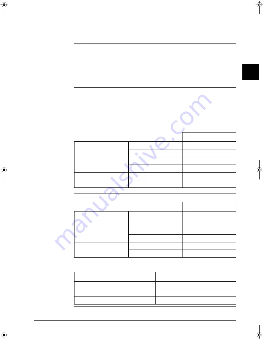
Indoor fan tap
Indoor cooling / Automatic
cooling
Thermostat OFF
L
Remote controller OFF
LL
Indoor heating / Automatic
heating
Thermostat OFF
LL
Remote controller OFF
LL
Indoor drying
Thermostat OFF
LL
Remote conntrolle OFF
LL
Indoor fan tap
Indoor cooling / Automatic
cooling
Thermostat OFF
Remote controller setting
Remote controller OFF
OFF
Indoor heating / Automatic
heating
Thermostat OFF
LL
Remote controller OFF
OFF
Indoor drying
Thermostat OFF
OFF
Remote controller OFF
OFF
Indoor fan tap
Indoor cooling / Automatic cooling
Remote controller setting
Indoor heating / Automatic heating
OFF
Indoor drying
L
RZQ - Final.book Page 33 Wednesday, September 8, 2004 8:40 AM
Summary of Contents for RZQ71~125B7V3B
Page 1: ...Service Manual ESIE04 01 RZQ71 125B7V3B Sky Air Inverter R 410A B series ...
Page 2: ......
Page 24: ...ESIE04 01 1 2 Part 1 System Outline 3 1 1 5 ...
Page 32: ...General Outline Outdoor Units ESIE04 01 1 10 Part 1 System Outline 3 1 1 4 5 ...
Page 64: ...General Outline Indoor Units ESIE04 01 1 42 Part 1 System Outline 3 1 1 4 5 ...
Page 76: ...Specifications ESIE04 01 1 54 Part 1 System Outline 3 1 1 4 5 ...
Page 92: ...Functional Diagrams ESIE04 01 1 70 Part 1 System Outline 3 1 1 4 5 ...
Page 94: ...ESIE04 01 1 72 Part 1 System Outline ...
Page 122: ...Wiring Diagrams ESIE04 01 1 100 Part 1 System Outline 3 1 1 4 5 ...
Page 140: ...ESIE04 01 2 2 Part 2 Functional Description 3 1 2 5 ...
Page 162: ...General Functionality ESIE04 01 2 24 Part 2 Functional Description 3 1 2 4 5 ...
Page 200: ...Outdoor Unit Functional Concept ESIE04 01 2 62 Part 2 Functional Description 3 1 2 4 5 ...
Page 202: ...ESIE04 01 3 2 Part 3 Troubleshooting 3 1 3 5 ...
Page 288: ...Error Codes Outdoor Units ESIE04 01 3 88 Part 3 Troubleshooting 3 1 3 4 5 ...
Page 312: ...Additional Checks for Troubleshooting ESIE04 01 3 112 Part 3 Troubleshooting 3 1 3 4 5 ...
Page 314: ...ESIE04 01 4 2 Part 4 Commissioning and Test Run 3 1 4 5 ...
Page 356: ...ESIE04 01 5 2 Part 5 Disassembly and Maintenance 3 1 5 ...
Page 484: ...ESIE04 01 viii Index 3 1 4 5 ...


