ESIE04-01
Troubleshooting
Part 3 – Troubleshooting
3–9
3
3
4
5
1
Troubleshooting
Caution
Be sure to turn off power switch before connect or disconnect connector, or parts damage may be
occurred.
YES
YES
YES
NO
NO
YES
Normal.
(Thermostat OFF by
outdoor temperature)
Turn on the power
switch or replace fuse.
NO
NO
YES
Replace the magnetic
switch or power
transistor.
Replace the PC board.
Replace the
compressor.
Check the thermistor.
NO
Air sensor
Indoor unit
PC board
Outdoor unit
PC board
Relay
Magnetic
switch
COMP
Input
to PC
board
Input
to PC
board
Output
from
PC
board
e
Output from
relay or
microcomputer
d
Output from
magnetic
switch or SW
circuit of
power
transistor
c
Output from
magnetic
switch or
U,V,W of
power
transistor
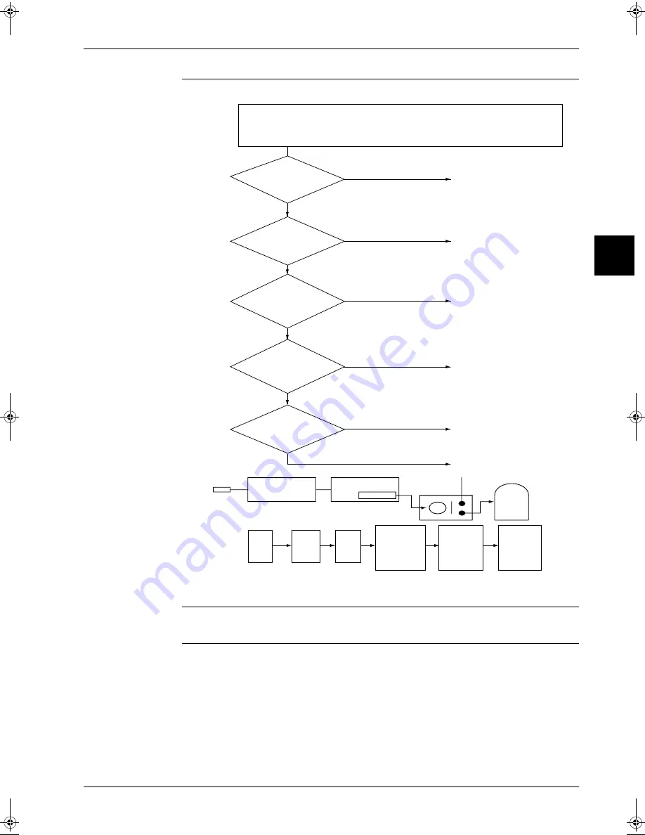
· Indoor unit fan runs at set airflow rate.
· (In cooling operation)
When air thermistor ambient temperature is higher than set temperature
· (In heating operation)
When air thermistor ambient temperature is lower than set temperature
Is the power
switch OFF or the fuse for
power switch
blown?
d
Is rated voltage
output from the magnetic
switch or power
transistor?
e
Is rated voltage output
from the PC board?
Is the heating
switch turned on at outdoor
temperature >30˚C
c
Is rated voltage
applied at
the compressor
terminals?
(S2576)
RZQ - Final.book Page 9 Wednesday, September 8, 2004 8:40 AM
Summary of Contents for RZQ71~125B7V3B
Page 1: ...Service Manual ESIE04 01 RZQ71 125B7V3B Sky Air Inverter R 410A B series ...
Page 2: ......
Page 24: ...ESIE04 01 1 2 Part 1 System Outline 3 1 1 5 ...
Page 32: ...General Outline Outdoor Units ESIE04 01 1 10 Part 1 System Outline 3 1 1 4 5 ...
Page 64: ...General Outline Indoor Units ESIE04 01 1 42 Part 1 System Outline 3 1 1 4 5 ...
Page 76: ...Specifications ESIE04 01 1 54 Part 1 System Outline 3 1 1 4 5 ...
Page 92: ...Functional Diagrams ESIE04 01 1 70 Part 1 System Outline 3 1 1 4 5 ...
Page 94: ...ESIE04 01 1 72 Part 1 System Outline ...
Page 122: ...Wiring Diagrams ESIE04 01 1 100 Part 1 System Outline 3 1 1 4 5 ...
Page 140: ...ESIE04 01 2 2 Part 2 Functional Description 3 1 2 5 ...
Page 162: ...General Functionality ESIE04 01 2 24 Part 2 Functional Description 3 1 2 4 5 ...
Page 200: ...Outdoor Unit Functional Concept ESIE04 01 2 62 Part 2 Functional Description 3 1 2 4 5 ...
Page 202: ...ESIE04 01 3 2 Part 3 Troubleshooting 3 1 3 5 ...
Page 288: ...Error Codes Outdoor Units ESIE04 01 3 88 Part 3 Troubleshooting 3 1 3 4 5 ...
Page 312: ...Additional Checks for Troubleshooting ESIE04 01 3 112 Part 3 Troubleshooting 3 1 3 4 5 ...
Page 314: ...ESIE04 01 4 2 Part 4 Commissioning and Test Run 3 1 4 5 ...
Page 356: ...ESIE04 01 5 2 Part 5 Disassembly and Maintenance 3 1 5 ...
Page 484: ...ESIE04 01 viii Index 3 1 4 5 ...


