ESIE04-01
Troubleshooting
Part 3 – Troubleshooting
3–17
3
3
4
5
1
Troubleshooting
Caution
Be sure to turn off power switch before connect or disconnect connector, or parts damage may be
occurred.
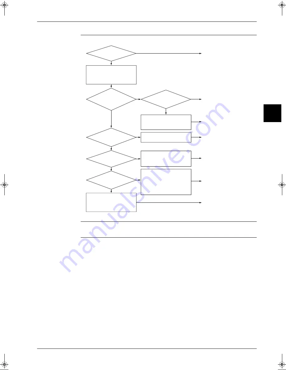
Measure the temperature of
suction air and supply air.
Temperature difference =
Suction air temp. – Supply air
temp.
Wait for a while.
No abnormality
No abnormality
Additional unit installation
should be considered
After vacuum drying, charge
correct amount of refrigerant.
Check each item
Check each item
Check each item
Temperature
difference for heating
should be between 14
and 30˚C.
Is the unit
in defrost mode?
Is the operation
current less than specified
level?
Does the
heat load increase after
installation of the
unit?
YES
YES
YES
YES
YES
YES
∗
Incorrect selection of model
∗
Affection of sunlight
∗
Affection of excessive fresh
air into room
Gas shortage possibly
generates trouble.
∗
Clogged air filter
∗
Soiled heat exchanger
∗
Malfunction of indoor fan
motor (Refer error code “A6”)
∗
Refrigerant overcharge
∗
Soiled heat exchanger
∗
Short circuit of discharge air
∗
Disturbing item in air flow
∗
Malfunction of fan motor of
outdoor unit
(Refer error code “E7”, “H7”)
∗
Insufficient compression of
compressor
∗
Insufficient circulation of
refrigerant
∗
Faulty expansion valve
NO
NO
NO
Does indoor
unit air flow
rate down?
NO
Is the level
of high pressure lower
than normal level?
NO
NO
(S1995)
RZQ - Final.book Page 17 Wednesday, September 8, 2004 8:40 AM
Summary of Contents for RZQ71~125B7V3B
Page 1: ...Service Manual ESIE04 01 RZQ71 125B7V3B Sky Air Inverter R 410A B series ...
Page 2: ......
Page 24: ...ESIE04 01 1 2 Part 1 System Outline 3 1 1 5 ...
Page 32: ...General Outline Outdoor Units ESIE04 01 1 10 Part 1 System Outline 3 1 1 4 5 ...
Page 64: ...General Outline Indoor Units ESIE04 01 1 42 Part 1 System Outline 3 1 1 4 5 ...
Page 76: ...Specifications ESIE04 01 1 54 Part 1 System Outline 3 1 1 4 5 ...
Page 92: ...Functional Diagrams ESIE04 01 1 70 Part 1 System Outline 3 1 1 4 5 ...
Page 94: ...ESIE04 01 1 72 Part 1 System Outline ...
Page 122: ...Wiring Diagrams ESIE04 01 1 100 Part 1 System Outline 3 1 1 4 5 ...
Page 140: ...ESIE04 01 2 2 Part 2 Functional Description 3 1 2 5 ...
Page 162: ...General Functionality ESIE04 01 2 24 Part 2 Functional Description 3 1 2 4 5 ...
Page 200: ...Outdoor Unit Functional Concept ESIE04 01 2 62 Part 2 Functional Description 3 1 2 4 5 ...
Page 202: ...ESIE04 01 3 2 Part 3 Troubleshooting 3 1 3 5 ...
Page 288: ...Error Codes Outdoor Units ESIE04 01 3 88 Part 3 Troubleshooting 3 1 3 4 5 ...
Page 312: ...Additional Checks for Troubleshooting ESIE04 01 3 112 Part 3 Troubleshooting 3 1 3 4 5 ...
Page 314: ...ESIE04 01 4 2 Part 4 Commissioning and Test Run 3 1 4 5 ...
Page 356: ...ESIE04 01 5 2 Part 5 Disassembly and Maintenance 3 1 5 ...
Page 484: ...ESIE04 01 viii Index 3 1 4 5 ...


