Troubleshooting
ESIE04-01
3–30
Part 3 – Troubleshooting
3
1
3
4
5
1.7
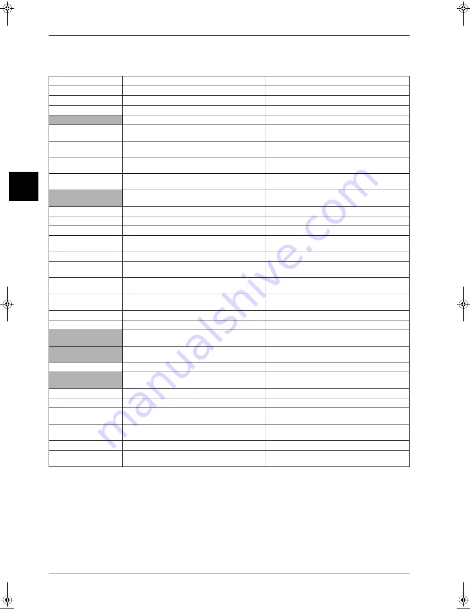
Overview of Error Codes
Malfunction Code
Contents/Processing
Remarks
A1
Failure of PC board ass’y for indoor unit
A3
Malfunction of drain water level system
A6
Indoor unit fan motor overload / overcurrent / lock (Note 1)
AF
Abnormal drain water level
Activation of float switch during compressor off.
AJ
Failure of capacity setting
Either capacity data is set incorrectly, or capacity
has not been set for the data IC
C4
Malfunction of heat exchanger temperature
sensor system
C5
Malfunction of gas piping temperature sensor
system
C9
Malfunction of suction air temperature sensor
system
CJ
Malfunction of remote control air temperature
sensor system
Failure of remote controller air thermistor.
Unit can be operated by indoor unit thermistor.
E0
Actuation of safety device (outdoor unit)
(Note 1)
E1
Outdoor unit PC board malfunction
E3
High pressure malfunction (outdoor unit)
E4
Abnormality of low pressure (outdoor)
Failure of low pressure sensor system.
Check if the stop valve open.
E5
Compressor motor lock malfunction
Compressor motor lock, incorrect wiring.
E7
Outdoor fan motor lock or outdoor fan
instantaneous overcurrent malfunction
E9
Malfunction of electronic expansion valve
(outdoor unit)
F3
Discharge pipe temperature malfunction
(outdoor unit)
H3
Failure of high pressure switch (outdoor unit)
H7
Malfunction of outdoor fan motor signal
H9
Malfunction of outdoor air temperature sensor
system (outdoor unit)
(Note 2)
J3
Malfunction of discharge pipe temperature
sensor system (outdoor unit)
J5
Suction pipe thermistor malfunction
Failure of suction pipe thermister system
J6
Malfunction of heat exchanger temperature
sensor system (outdoor unit)
(Note 2)
JC
Malfunction of suction pressure sensor
Failure of suction pressure sensor system
L4
Radiation fin temperature rise
Malfunction of inverter cooling
L5
Instantaneous over current
Possibility of compressor motor grounding or
shortage of motor winding
L8
Electronic thermal
Possibility of compressor overload, open circuit
in compressor motor
L9
Stall prevention
Possibility of compressor seizing
LC
Malfunction of transmission system (between
control PCB and inverter PCB)
RZQ - Final.book Page 30 Wednesday, September 8, 2004 8:40 AM
Summary of Contents for RZQ71~125B7V3B
Page 1: ...Service Manual ESIE04 01 RZQ71 125B7V3B Sky Air Inverter R 410A B series ...
Page 2: ......
Page 24: ...ESIE04 01 1 2 Part 1 System Outline 3 1 1 5 ...
Page 32: ...General Outline Outdoor Units ESIE04 01 1 10 Part 1 System Outline 3 1 1 4 5 ...
Page 64: ...General Outline Indoor Units ESIE04 01 1 42 Part 1 System Outline 3 1 1 4 5 ...
Page 76: ...Specifications ESIE04 01 1 54 Part 1 System Outline 3 1 1 4 5 ...
Page 92: ...Functional Diagrams ESIE04 01 1 70 Part 1 System Outline 3 1 1 4 5 ...
Page 94: ...ESIE04 01 1 72 Part 1 System Outline ...
Page 122: ...Wiring Diagrams ESIE04 01 1 100 Part 1 System Outline 3 1 1 4 5 ...
Page 140: ...ESIE04 01 2 2 Part 2 Functional Description 3 1 2 5 ...
Page 162: ...General Functionality ESIE04 01 2 24 Part 2 Functional Description 3 1 2 4 5 ...
Page 200: ...Outdoor Unit Functional Concept ESIE04 01 2 62 Part 2 Functional Description 3 1 2 4 5 ...
Page 202: ...ESIE04 01 3 2 Part 3 Troubleshooting 3 1 3 5 ...
Page 288: ...Error Codes Outdoor Units ESIE04 01 3 88 Part 3 Troubleshooting 3 1 3 4 5 ...
Page 312: ...Additional Checks for Troubleshooting ESIE04 01 3 112 Part 3 Troubleshooting 3 1 3 4 5 ...
Page 314: ...ESIE04 01 4 2 Part 4 Commissioning and Test Run 3 1 4 5 ...
Page 356: ...ESIE04 01 5 2 Part 5 Disassembly and Maintenance 3 1 5 ...
Page 484: ...ESIE04 01 viii Index 3 1 4 5 ...


