ESIE04-01
Troubleshooting
Part 3 – Troubleshooting
3–33
3
3
4
5
1
1.8.2
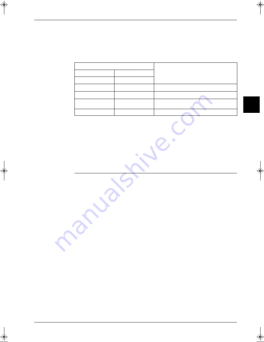
Troubleshooting by LED on outdoor unit PCB
The following diagnosis can be conducted by turning on the power switch and checking the LED
indication on the printed circuit board of the outdoor unit.
w
: LED on /
x
: LED off /
c
: LED blinks / — : Not used for diagnosis
Notes:
1
Turn off the power switch, and turn it on again after 5 seconds or more. Check the error condition,
and diagnose the problem.
2
Turn off the power switch. After 5 seconds or more, disconnect the connection wire (2). Then turn
on the power switch. If the HAP on the outdoor unit PCB flashes after about 10 seconds, the indoor
unit PCB is faulty.
3
Also check for open phase.
Remark:
The error detection monitor continues to indication the previously generated error until the power
switch is turned off.
Be sure to turn off the power switch after inspection.
LED detection
Description
HAP
H1P
(Green)
(Red)
c
x
Normal
w
—
Faulty outdoor unit PCB (Note 1)
x
—
Power supply abnormality, or faulty outdoor unit
PCB (Note 2)
c
w
Activation of protection device (Note 3)
RZQ - Final.book Page 33 Wednesday, September 8, 2004 8:40 AM
Summary of Contents for RZQ71~125B7V3B
Page 1: ...Service Manual ESIE04 01 RZQ71 125B7V3B Sky Air Inverter R 410A B series ...
Page 2: ......
Page 24: ...ESIE04 01 1 2 Part 1 System Outline 3 1 1 5 ...
Page 32: ...General Outline Outdoor Units ESIE04 01 1 10 Part 1 System Outline 3 1 1 4 5 ...
Page 64: ...General Outline Indoor Units ESIE04 01 1 42 Part 1 System Outline 3 1 1 4 5 ...
Page 76: ...Specifications ESIE04 01 1 54 Part 1 System Outline 3 1 1 4 5 ...
Page 92: ...Functional Diagrams ESIE04 01 1 70 Part 1 System Outline 3 1 1 4 5 ...
Page 94: ...ESIE04 01 1 72 Part 1 System Outline ...
Page 122: ...Wiring Diagrams ESIE04 01 1 100 Part 1 System Outline 3 1 1 4 5 ...
Page 140: ...ESIE04 01 2 2 Part 2 Functional Description 3 1 2 5 ...
Page 162: ...General Functionality ESIE04 01 2 24 Part 2 Functional Description 3 1 2 4 5 ...
Page 200: ...Outdoor Unit Functional Concept ESIE04 01 2 62 Part 2 Functional Description 3 1 2 4 5 ...
Page 202: ...ESIE04 01 3 2 Part 3 Troubleshooting 3 1 3 5 ...
Page 288: ...Error Codes Outdoor Units ESIE04 01 3 88 Part 3 Troubleshooting 3 1 3 4 5 ...
Page 312: ...Additional Checks for Troubleshooting ESIE04 01 3 112 Part 3 Troubleshooting 3 1 3 4 5 ...
Page 314: ...ESIE04 01 4 2 Part 4 Commissioning and Test Run 3 1 4 5 ...
Page 356: ...ESIE04 01 5 2 Part 5 Disassembly and Maintenance 3 1 5 ...
Page 484: ...ESIE04 01 viii Index 3 1 4 5 ...


