ESIE04-01
Error Codes: Outdoor Units
Part 3 – Troubleshooting
3–77
3
3
4
5
1
Troubleshooting
Caution
Be sure to turn off power switch before connect or disconnect connector, or parts damage may be
occurred.
NO
YES
YES
NO
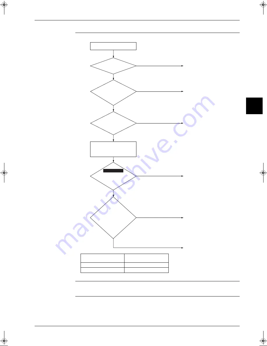
Insufficient pressure equalization
Check refrigerant system.
Compressor inspection
Inspect according to the diagnosis
procedure for abnormal noises,
vibration, operating status, etc.
of the compressor.
Compressor overload
Inspection of the compressor
and refrigerant is required.
0
Approximate value
Detection value
Is
the difference
between high and low
pressure before startup
not more than
0.2MPa?
Is the
secondary current
of the inverter higher than
0
A (see below) for
each phase?
Turn the main power supply
off, and then disconnect the
connection between the
compressor and inverter.
NO
Replace the inverter PC board.
YES
NO
Replace the inverter PC board.
YES
Is the
inverter
output voltage
generated approximately
at the same increasing
speed on each phase after
turning on again?
(*)
(U-V, V-W,
W-U)
* When operating compressor with
compressor output line disconnected, the
compressor stops due to malfunction after
elapsed time of 5 seconds. Therefore,
check the voltage increase for 5 seconds.
Continuity check in the
power transistor (IGBT)
Is the continuity
normal?
Check No. 10
NO
YES
Open the stop valve.
Is the stop valve open?
Check the installation
conditions.
(S2594)
RZQ71
RZQ100 ~ 125
22.0A
33.0A
RZQ - Final.book Page 77 Wednesday, September 8, 2004 8:40 AM
Summary of Contents for RZQ71~125B7V3B
Page 1: ...Service Manual ESIE04 01 RZQ71 125B7V3B Sky Air Inverter R 410A B series ...
Page 2: ......
Page 24: ...ESIE04 01 1 2 Part 1 System Outline 3 1 1 5 ...
Page 32: ...General Outline Outdoor Units ESIE04 01 1 10 Part 1 System Outline 3 1 1 4 5 ...
Page 64: ...General Outline Indoor Units ESIE04 01 1 42 Part 1 System Outline 3 1 1 4 5 ...
Page 76: ...Specifications ESIE04 01 1 54 Part 1 System Outline 3 1 1 4 5 ...
Page 92: ...Functional Diagrams ESIE04 01 1 70 Part 1 System Outline 3 1 1 4 5 ...
Page 94: ...ESIE04 01 1 72 Part 1 System Outline ...
Page 122: ...Wiring Diagrams ESIE04 01 1 100 Part 1 System Outline 3 1 1 4 5 ...
Page 140: ...ESIE04 01 2 2 Part 2 Functional Description 3 1 2 5 ...
Page 162: ...General Functionality ESIE04 01 2 24 Part 2 Functional Description 3 1 2 4 5 ...
Page 200: ...Outdoor Unit Functional Concept ESIE04 01 2 62 Part 2 Functional Description 3 1 2 4 5 ...
Page 202: ...ESIE04 01 3 2 Part 3 Troubleshooting 3 1 3 5 ...
Page 288: ...Error Codes Outdoor Units ESIE04 01 3 88 Part 3 Troubleshooting 3 1 3 4 5 ...
Page 312: ...Additional Checks for Troubleshooting ESIE04 01 3 112 Part 3 Troubleshooting 3 1 3 4 5 ...
Page 314: ...ESIE04 01 4 2 Part 4 Commissioning and Test Run 3 1 4 5 ...
Page 356: ...ESIE04 01 5 2 Part 5 Disassembly and Maintenance 3 1 5 ...
Page 484: ...ESIE04 01 viii Index 3 1 4 5 ...


