ESIE04-01
Additional Checks for Troubleshooting
Part 3 – Troubleshooting
3–103
3
3
4
5
1
5.7
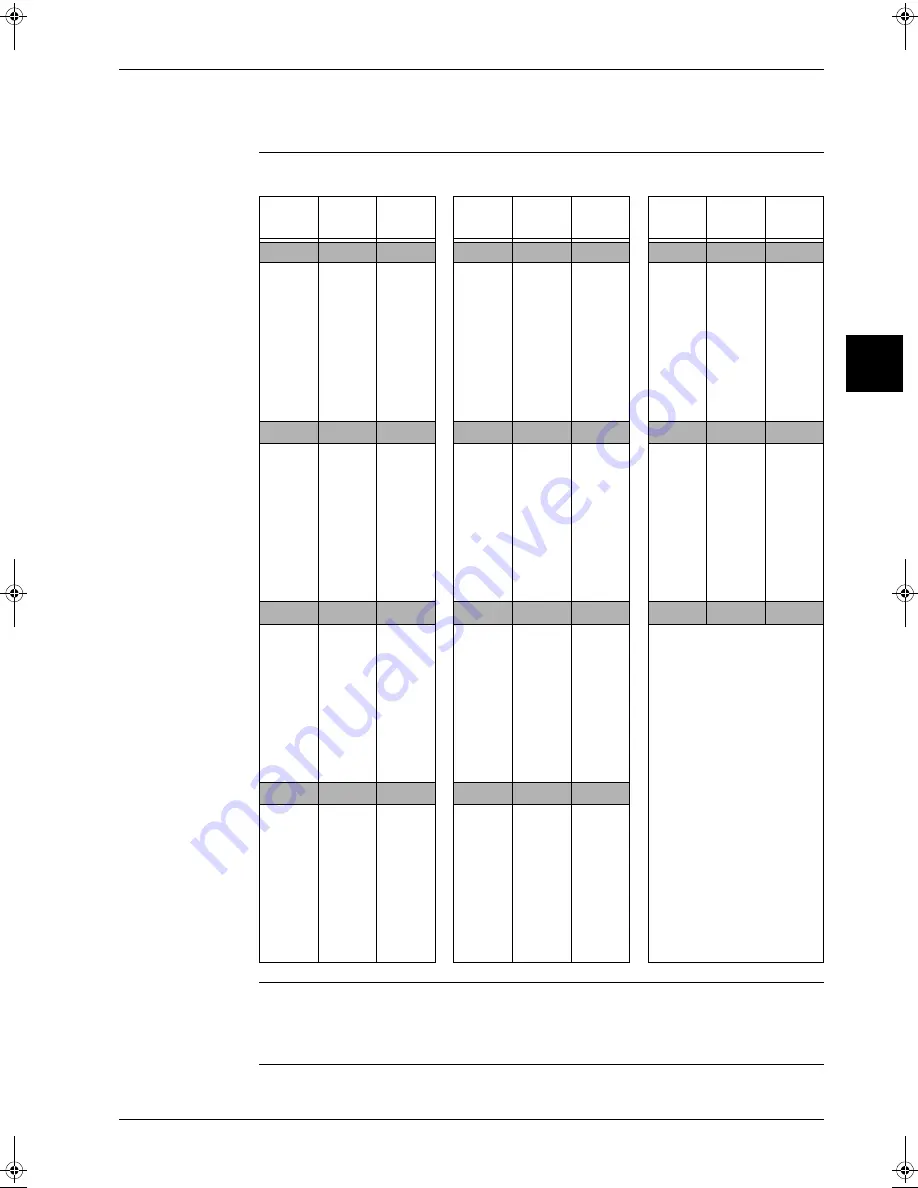
Resistance Conversion Table (Ambient, Coil, Fin)
Temperature –
resistance
The table below is the thermistor (R1T and R2T) temperature – resistance conversion table.
Applicable sensors
A: Indoor: R1T, R2T, R3T
Outdoor: R1T, R2T, R4T
B: Outdoor: R5T
Temp.
(°C)
A (k
Ω
)
B (k
Ω
)
Temp.
(°C)
A (k
Ω
)
B (k
Ω
)
Temp.
(°C)
A (k
Ω
)
B (k
Ω
)
-20
197.81
192.08
20
25.01
24.45
60
4.96
4.87
-19
-18
-17
-16
-15
-14
-13
-12
-11
186.53
175.97
166.07
156.80
148.10
139.94
132.28
125.09
118.34
181.16
170.94
161.36
152.38
143.96
136.05
128.63
121.66
115.12
21
22
23
24
25
26
27
28
29
23.91
22.85
21.85
20.90
20.00
19.14
18.32
17.54
16.80
23.37
22.35
21.37
20.45
19.56
18.73
17.93
17.17
16.45
61
62
63
64
65
66
67
68
69
4.79
4.62
4.46
4.30
4.16
4.01
3.88
3.75
3.62
4.70
4.54
4.38
4.23
4.08
3.94
3.81
3.68
3.56
-10
111.99
108.96
30
16.10
15.76
70
3.50
3.44
-9
-8
-7
-6
-5
-4
-3
-2
-1
106.03
100.41
95.14
90.17
85.49
81.08
76.93
73.01
69.32
103.18
97.73
92.61
87.79
83.25
78.97
74.94
71.14
67.56
31
32
33
34
35
36
37
38
39
15.43
14.79
14.18
13.59
13.04
12.51
12.01
11.52
11.06
15.10
14.48
13.88
13.31
12.77
12.25
11.76
11.29
10.84
71
72
73
74
75
76
77
78
79
3.38
3.27
3.16
3.06
2.96
2.86
2.77
2.68
2.60
3.32
3.21
3.11
3.01
2.91
2.82
2.72
2.64
2.55
0
65.84
64.17
40
10.63
10.41
80
2.51
2.47
1
2
3
4
5
6
7
8
9
62.54
59.43
56.49
53.71
51.09
48.61
46.26
44.05
41.95
60.96
57.94
55.08
52.38
49.83
47.42
45.14
42.98
40.94
41
42
43
44
45
46
47
48
49
10.21
9.81
9.42
9.06
8.71
8.37
8.05
7.75
7.46
10.00
9.61
9.24
8.88
8.54
8.21
7.90
7.60
7.31
—
10
39.96
39.01
50
7.18
7.04
11
12
13
14
15
16
17
18
19
38.08
36.30
34.62
33.02
31.50
30.06
28.70
27.41
26.18
37.18
35.45
33.81
32.25
30.77
29.37
28.05
26.78
25.59
51
52
53
54
55
56
57
58
59
6.91
6.65
6.41
6.65
6.41
6.18
5.95
5.74
5.14
6.78
6.53
6.53
6.53
6.29
6.06
5.84
5.43
5.05
RZQ - Final.book Page 103 Wednesday, September 8, 2004 8:40 AM
Summary of Contents for RZQ71~125B7V3B
Page 1: ...Service Manual ESIE04 01 RZQ71 125B7V3B Sky Air Inverter R 410A B series ...
Page 2: ......
Page 24: ...ESIE04 01 1 2 Part 1 System Outline 3 1 1 5 ...
Page 32: ...General Outline Outdoor Units ESIE04 01 1 10 Part 1 System Outline 3 1 1 4 5 ...
Page 64: ...General Outline Indoor Units ESIE04 01 1 42 Part 1 System Outline 3 1 1 4 5 ...
Page 76: ...Specifications ESIE04 01 1 54 Part 1 System Outline 3 1 1 4 5 ...
Page 92: ...Functional Diagrams ESIE04 01 1 70 Part 1 System Outline 3 1 1 4 5 ...
Page 94: ...ESIE04 01 1 72 Part 1 System Outline ...
Page 122: ...Wiring Diagrams ESIE04 01 1 100 Part 1 System Outline 3 1 1 4 5 ...
Page 140: ...ESIE04 01 2 2 Part 2 Functional Description 3 1 2 5 ...
Page 162: ...General Functionality ESIE04 01 2 24 Part 2 Functional Description 3 1 2 4 5 ...
Page 200: ...Outdoor Unit Functional Concept ESIE04 01 2 62 Part 2 Functional Description 3 1 2 4 5 ...
Page 202: ...ESIE04 01 3 2 Part 3 Troubleshooting 3 1 3 5 ...
Page 288: ...Error Codes Outdoor Units ESIE04 01 3 88 Part 3 Troubleshooting 3 1 3 4 5 ...
Page 312: ...Additional Checks for Troubleshooting ESIE04 01 3 112 Part 3 Troubleshooting 3 1 3 4 5 ...
Page 314: ...ESIE04 01 4 2 Part 4 Commissioning and Test Run 3 1 4 5 ...
Page 356: ...ESIE04 01 5 2 Part 5 Disassembly and Maintenance 3 1 5 ...
Page 484: ...ESIE04 01 viii Index 3 1 4 5 ...


