Pre-Test Run Checks
ESIE04-01
4–4
Part 4 – Commissioning and Test Run
3
1
4
5
1.2
Test Run Checks
Checks before test
run
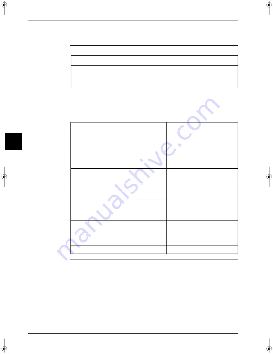
Before carrying out a test run, proceed as follows:
Test run checks
To carry out a test run, check the following:
P
Check that the temperature setting of the remote controller is at the lowest level in cooling mode
or use test mode.
P
Go through the following checklist:
Step
Action
1
Make sure the voltage at the primary side of the safety breaker is:
P
230 V ± 10%
2
Fully open the liquid and the gas stop valve.
Checkpoints
Cautions or warnings
Are all units securely installed?
P
Dangerous for turning over during
storm.
P
Possible damage to pipe
connections.
Is the earth wire installed according to the applicable
local standard?
Dangerous if electric leakage occurs.
Are all air inlets and outlets of the indoor and outdoor
units unobstructed?
P
Poor cooling.
P
Poor heating.
Does the drain flow out smoothly?
Water leakage.
Is piping adequately heat-insulated?
Water leakage.
Have the connections been checked for gas leakage?
P
Poor cooling.
P
Poor heating.
P
Stop.
Is the supply voltage conform to the specifications on
the name plate?
Incorrect operation.
Are the cable sizes as specified and according to local
regulations?
Damage of cables.
Are the remote controller signals received by the unit?
No operation.
RZQ - Final.book Page 4 Wednesday, September 8, 2004 8:40 AM
Summary of Contents for RZQ71~125B7V3B
Page 1: ...Service Manual ESIE04 01 RZQ71 125B7V3B Sky Air Inverter R 410A B series ...
Page 2: ......
Page 24: ...ESIE04 01 1 2 Part 1 System Outline 3 1 1 5 ...
Page 32: ...General Outline Outdoor Units ESIE04 01 1 10 Part 1 System Outline 3 1 1 4 5 ...
Page 64: ...General Outline Indoor Units ESIE04 01 1 42 Part 1 System Outline 3 1 1 4 5 ...
Page 76: ...Specifications ESIE04 01 1 54 Part 1 System Outline 3 1 1 4 5 ...
Page 92: ...Functional Diagrams ESIE04 01 1 70 Part 1 System Outline 3 1 1 4 5 ...
Page 94: ...ESIE04 01 1 72 Part 1 System Outline ...
Page 122: ...Wiring Diagrams ESIE04 01 1 100 Part 1 System Outline 3 1 1 4 5 ...
Page 140: ...ESIE04 01 2 2 Part 2 Functional Description 3 1 2 5 ...
Page 162: ...General Functionality ESIE04 01 2 24 Part 2 Functional Description 3 1 2 4 5 ...
Page 200: ...Outdoor Unit Functional Concept ESIE04 01 2 62 Part 2 Functional Description 3 1 2 4 5 ...
Page 202: ...ESIE04 01 3 2 Part 3 Troubleshooting 3 1 3 5 ...
Page 288: ...Error Codes Outdoor Units ESIE04 01 3 88 Part 3 Troubleshooting 3 1 3 4 5 ...
Page 312: ...Additional Checks for Troubleshooting ESIE04 01 3 112 Part 3 Troubleshooting 3 1 3 4 5 ...
Page 314: ...ESIE04 01 4 2 Part 4 Commissioning and Test Run 3 1 4 5 ...
Page 356: ...ESIE04 01 5 2 Part 5 Disassembly and Maintenance 3 1 5 ...
Page 484: ...ESIE04 01 viii Index 3 1 4 5 ...


