ESIE04-01
Field settings
Part 4 – Commissioning and Test Run
4–35
3
4
5
1
Capacity
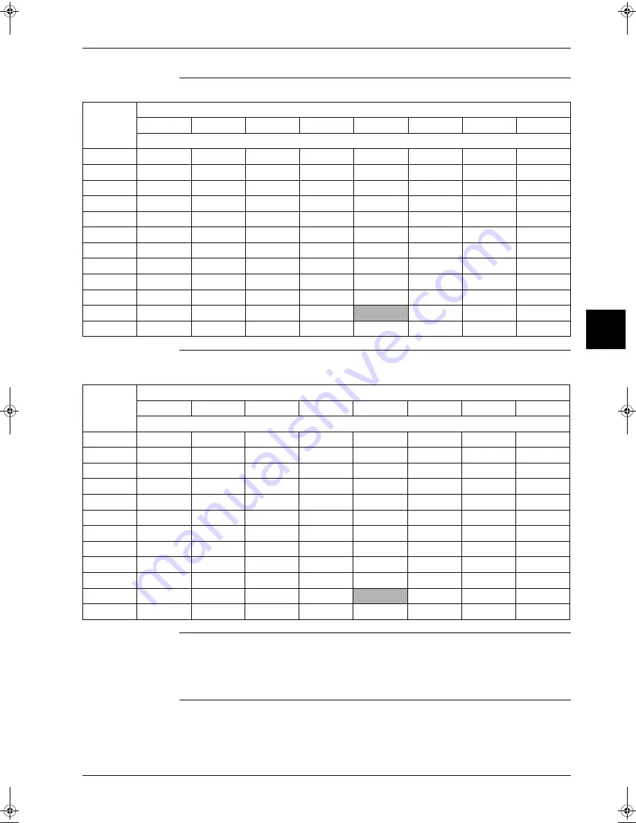
When "low humidity application" is selected. Field setting 16(26)-2-03:
Capacity
When "low humidity appli freeze up operation prevention" is selected. Field setting
16(26)-2-04:
Note:
P
Operation range on indoor side expanded from minimum 12°CWB to 11°CWB when using LH
setting.
P
Do not use a setpoint below 20°C to avoid operation out of the indoor operation range (11°CWB).
P
Be sure to set the indoor fan to high speed.
Outdoor
Temp.
(°C-DB)
Indoot Temp. (°C-WB°
11
14
16
18
19
20
22
24
Capacity (% of standard point)
-15
0.62
0.76
0.86
0.95
1.00
1.02
1.07
1.11
-10
0.62
0.76
0.86
0.95
1.00
1.02
1.07
1.11
-5
0.62
0.81
0.91
1.01
1.06
1.16
1.21
1.26
0
0.62
0.81
0.91
1.01
1.06
1.16
1.21
1.26
5
0.62
0.81
0.91
1.01
1.06
1.16
1.21
1.26
10
0.62
0.81
0.91
1.01
1.06
1.16
1.21
1.26
15
0.62
0.81
0.91
1.01
1.12
1.14
1.19
1.24
20
0.62
0.81
0.91
1.07
1.10
1.12
1.16
1.21
25
0.62
0.81
0.91
1.05
1.07
1.09
1.13
1.18
30
0.61
0.81
0.91
1.01
1.04
1.06
1.10
1.14
35
0.61
0.81
0.94
0.98
1.00
1.02
1.06
1.11
40
0.61
0.81
0.90
0.94
0.96
0.98
1.02
1.06
Outdoor
Temp.
(°C-DB)
Indoot Temp. (°C-WB°
11
14
16
18
19
20
22
24
Capacity (% of standard point)
-15
0.51
0.68
0.78
0.95
1.01
1.06
1.16
1.26
-10
0.51
0.68
0.78
0.95
1.01
1.06
1.16
1.26
-5
0.51
0.68
0.78
0.95
1.01
1.06
1.16
1.26
0
0.51
0.68
0.78
0.95
1.01
1.06
1.16
1.26
5
0.51
0.68
0.78
0.95
1.01
1.06
1.16
1.26
10
0.51
0.68
0.78
0.95
1.01
1.06
1.16
1.26
15
0.51
0.68
0.78
0.95
1.01
1.06
1.16
1.24
20
0.51
0.68
0.78
0.95
1.01
1.06
1.16
1.21
25
0.51
0.68
0.78
0.95
1.00
1.06
1.13
1.18
30
0.51
0.68
0.78
0.95
1.00
1.05
1.10
1.14
35
0.51
0.68
0.78
0.95
1.00
1.02
1.06
1.11
40
0.51
0.67
0.78
0.94
0.96
0.98
1.02
1.06
RZQ - Final.book Page 35 Wednesday, September 8, 2004 8:40 AM
Summary of Contents for RZQ71~125B7V3B
Page 1: ...Service Manual ESIE04 01 RZQ71 125B7V3B Sky Air Inverter R 410A B series ...
Page 2: ......
Page 24: ...ESIE04 01 1 2 Part 1 System Outline 3 1 1 5 ...
Page 32: ...General Outline Outdoor Units ESIE04 01 1 10 Part 1 System Outline 3 1 1 4 5 ...
Page 64: ...General Outline Indoor Units ESIE04 01 1 42 Part 1 System Outline 3 1 1 4 5 ...
Page 76: ...Specifications ESIE04 01 1 54 Part 1 System Outline 3 1 1 4 5 ...
Page 92: ...Functional Diagrams ESIE04 01 1 70 Part 1 System Outline 3 1 1 4 5 ...
Page 94: ...ESIE04 01 1 72 Part 1 System Outline ...
Page 122: ...Wiring Diagrams ESIE04 01 1 100 Part 1 System Outline 3 1 1 4 5 ...
Page 140: ...ESIE04 01 2 2 Part 2 Functional Description 3 1 2 5 ...
Page 162: ...General Functionality ESIE04 01 2 24 Part 2 Functional Description 3 1 2 4 5 ...
Page 200: ...Outdoor Unit Functional Concept ESIE04 01 2 62 Part 2 Functional Description 3 1 2 4 5 ...
Page 202: ...ESIE04 01 3 2 Part 3 Troubleshooting 3 1 3 5 ...
Page 288: ...Error Codes Outdoor Units ESIE04 01 3 88 Part 3 Troubleshooting 3 1 3 4 5 ...
Page 312: ...Additional Checks for Troubleshooting ESIE04 01 3 112 Part 3 Troubleshooting 3 1 3 4 5 ...
Page 314: ...ESIE04 01 4 2 Part 4 Commissioning and Test Run 3 1 4 5 ...
Page 356: ...ESIE04 01 5 2 Part 5 Disassembly and Maintenance 3 1 5 ...
Page 484: ...ESIE04 01 viii Index 3 1 4 5 ...


