Disassembly and Maintenance: Outdoor Units
ESIE04-01
5–12
Part 5 – Disassembly and Maintenance
3
1
55
1.2.6
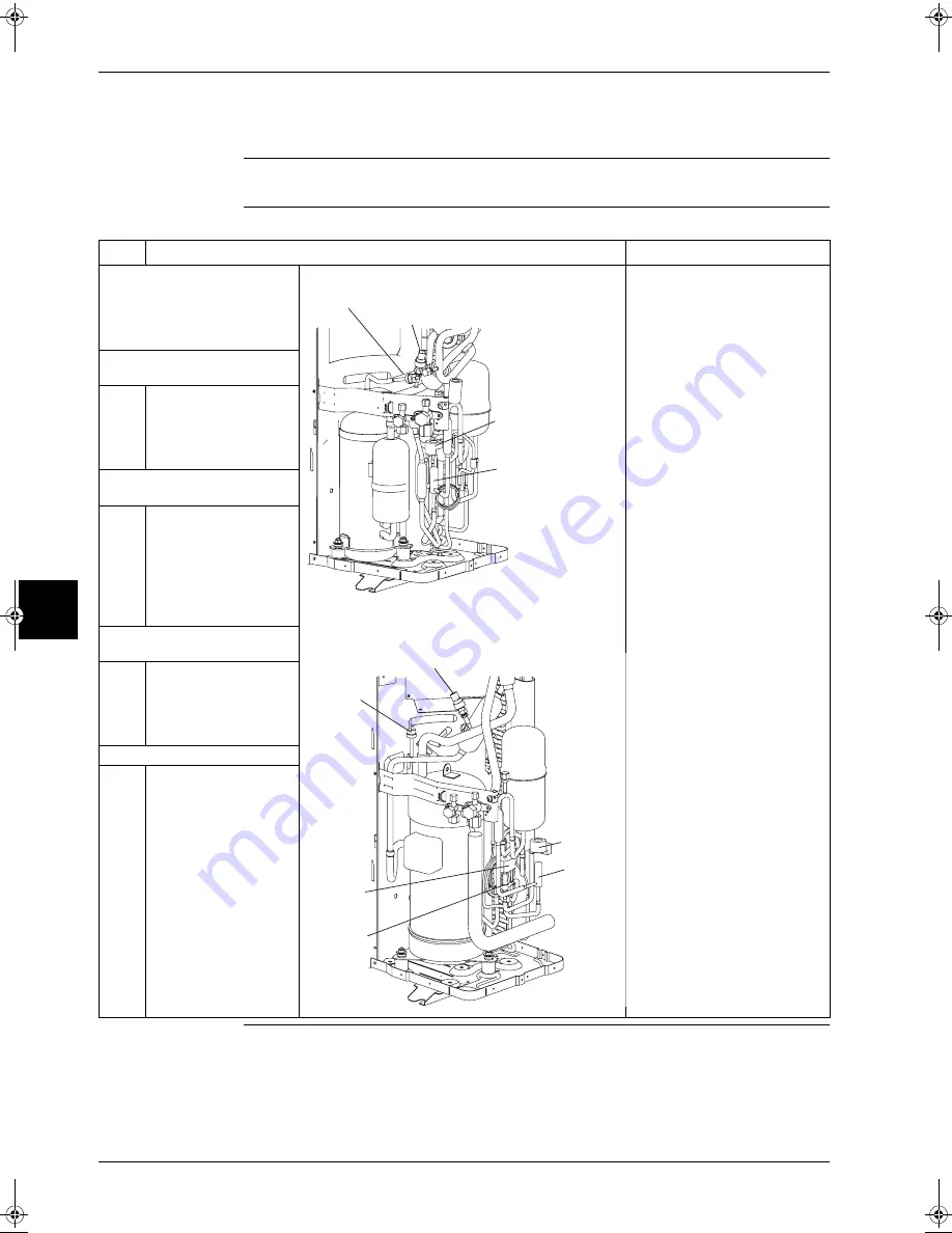
Removal of Low Pressure Sensor, Electronic Expansion Valve, and Others
Warning
Be sure to wait 10 minutes or more after turning off all power supplies before disassembling work.
Procedure
Step
Procedure
Points
P
Remove the parts related to
the outside panel and the
switch box in accordance with
the Removal Procedure for
Outside Panel and others.
P
RZQ71B7V3B
1
Remove the low pressure
sensor
1
Rotate the connection
port on the low pressure
sensor with a spanner or
the like and then remove
this sensor.
2
Remove the electronic
expansion valve
1
Pull out the coil from the
electronic expansion
valve upward.
2
Strip off the brazed
sections in two places on
the body of the valve and
then remove this body.
3
Remove the high pressure
switch
P
RZQ100~125B7V3B
1
Disconnect the terminals
from the high pressure
switch and then strip off
the brazed section on the
switch.
4
Remove the solenoid valve
(Only on RZQ100~
125B7V3B)
1
Unscrew a single screw
from the coil of the
solenoid valve and then
remove this coil.
2
Strip off the brazed
sections in two places on
the main unit of the
solenoid valve and then
remove this body.
High pressure switch
Low pressure sensor
Coil of electronic
expansion valve
Body of electronic
expansion valve
Low pressure sensor
High
pressure
switch
Coil of
electronic
expansion
valve
Body of
electronic
expansion
valve
Coil of
solenoid
valve
Body of
solenoid
valve
RZQ - Final.book Page 12 Wednesday, September 8, 2004 8:40 AM
Summary of Contents for RZQ71~125B7V3B
Page 1: ...Service Manual ESIE04 01 RZQ71 125B7V3B Sky Air Inverter R 410A B series ...
Page 2: ......
Page 24: ...ESIE04 01 1 2 Part 1 System Outline 3 1 1 5 ...
Page 32: ...General Outline Outdoor Units ESIE04 01 1 10 Part 1 System Outline 3 1 1 4 5 ...
Page 64: ...General Outline Indoor Units ESIE04 01 1 42 Part 1 System Outline 3 1 1 4 5 ...
Page 76: ...Specifications ESIE04 01 1 54 Part 1 System Outline 3 1 1 4 5 ...
Page 92: ...Functional Diagrams ESIE04 01 1 70 Part 1 System Outline 3 1 1 4 5 ...
Page 94: ...ESIE04 01 1 72 Part 1 System Outline ...
Page 122: ...Wiring Diagrams ESIE04 01 1 100 Part 1 System Outline 3 1 1 4 5 ...
Page 140: ...ESIE04 01 2 2 Part 2 Functional Description 3 1 2 5 ...
Page 162: ...General Functionality ESIE04 01 2 24 Part 2 Functional Description 3 1 2 4 5 ...
Page 200: ...Outdoor Unit Functional Concept ESIE04 01 2 62 Part 2 Functional Description 3 1 2 4 5 ...
Page 202: ...ESIE04 01 3 2 Part 3 Troubleshooting 3 1 3 5 ...
Page 288: ...Error Codes Outdoor Units ESIE04 01 3 88 Part 3 Troubleshooting 3 1 3 4 5 ...
Page 312: ...Additional Checks for Troubleshooting ESIE04 01 3 112 Part 3 Troubleshooting 3 1 3 4 5 ...
Page 314: ...ESIE04 01 4 2 Part 4 Commissioning and Test Run 3 1 4 5 ...
Page 356: ...ESIE04 01 5 2 Part 5 Disassembly and Maintenance 3 1 5 ...
Page 484: ...ESIE04 01 viii Index 3 1 4 5 ...


