ESIE04-01
Disassembly and Maintenance: Outdoor Units
Part 5 – Disassembly and Maintenance
5–15
3
5
1
5
1.2.9
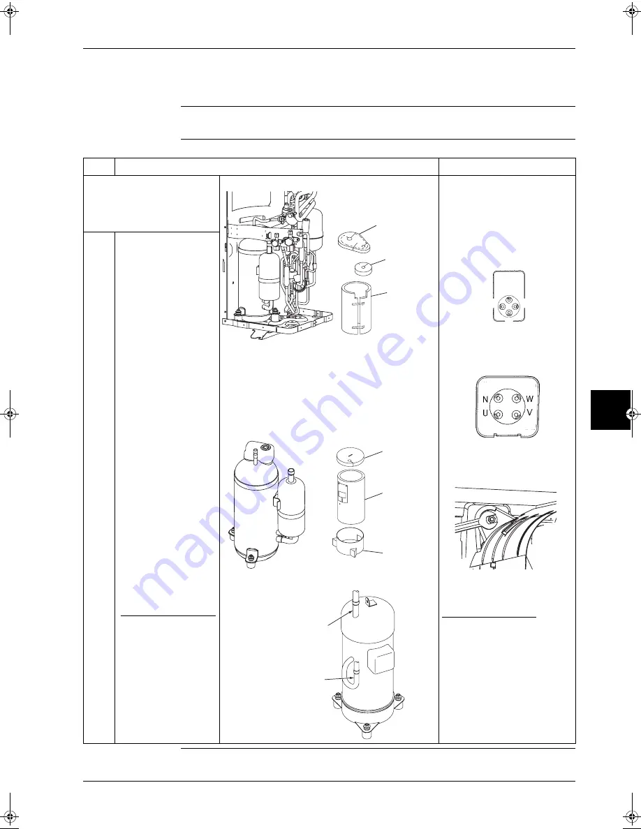
Removal of Compressor
Warning
Be sure to wait 10 minutes or more after turning off all power supplies before disassembling work.
Procedure
Step
Procedure
Points
P
Remove the parts related to
the outside panel and the
switch box in accordance with
the Removal Procedure for
Outside Panel and others.
P
RZQ71B7V3B
P
Compressor for RZQ71B7V3B
P
Compressor for RZQ100~125B7V3B
P
Check to be sure there are no
more refrigerants left in the
unit before starting this
removal.
P
Color of terminal pins
P
RZQ71B7V3B
P
RZQ100-125B7V3B
P
One out of the two nuts that fix
the compressor is located
outside the partition plate.
Caution:
For RZQ100-125B7V3B
If the brazed sections are directly
stripped off from the pipes, oil
may catch fire.
Be sure to cut the pipes in
advance with a pipe cutter.
1
Unscrew the five screws
from the stop valve
mounting plate.
2
Disconnect the gas
piping and liquid piping.
3
Push the protrusion from
both sides to remove the
terminal cover.
4
Remove the lead wires
from the terminal pins.
5
Remove the sound
insulation (1), (2), and
(3), and
vibration-isolating putty.
6
Unlock the nuts (*) that fix
the compressor.
A total of three nuts are
provided.
7
Strip off the brazed
sections (in two places*).
*For RZQ100-125B7V3B
Before stripping off the
brazed sections, be sure
to cut the suction and
discharge pipes with a
pipe cutter.
(See Caution in the
column of Points.)
8
Lift up the compressor to
pull out it.
Sound
insulation (2)
Vibration-
isolating putty
Sound
insulation (1)
Sound
insulation (2)
Sound
insulation (1)
Sound
insulation (3)
Cut here
(on suction pipe)
Cut here
(on discharge pipe)
(Yellow)
V
N
(Brown)
U (Red)
(Blue) W
(Brown)
(Blue)
(Red)
(White)
RZQ - Final.book Page 15 Wednesday, September 8, 2004 8:40 AM
Summary of Contents for RZQ71~125B7V3B
Page 1: ...Service Manual ESIE04 01 RZQ71 125B7V3B Sky Air Inverter R 410A B series ...
Page 2: ......
Page 24: ...ESIE04 01 1 2 Part 1 System Outline 3 1 1 5 ...
Page 32: ...General Outline Outdoor Units ESIE04 01 1 10 Part 1 System Outline 3 1 1 4 5 ...
Page 64: ...General Outline Indoor Units ESIE04 01 1 42 Part 1 System Outline 3 1 1 4 5 ...
Page 76: ...Specifications ESIE04 01 1 54 Part 1 System Outline 3 1 1 4 5 ...
Page 92: ...Functional Diagrams ESIE04 01 1 70 Part 1 System Outline 3 1 1 4 5 ...
Page 94: ...ESIE04 01 1 72 Part 1 System Outline ...
Page 122: ...Wiring Diagrams ESIE04 01 1 100 Part 1 System Outline 3 1 1 4 5 ...
Page 140: ...ESIE04 01 2 2 Part 2 Functional Description 3 1 2 5 ...
Page 162: ...General Functionality ESIE04 01 2 24 Part 2 Functional Description 3 1 2 4 5 ...
Page 200: ...Outdoor Unit Functional Concept ESIE04 01 2 62 Part 2 Functional Description 3 1 2 4 5 ...
Page 202: ...ESIE04 01 3 2 Part 3 Troubleshooting 3 1 3 5 ...
Page 288: ...Error Codes Outdoor Units ESIE04 01 3 88 Part 3 Troubleshooting 3 1 3 4 5 ...
Page 312: ...Additional Checks for Troubleshooting ESIE04 01 3 112 Part 3 Troubleshooting 3 1 3 4 5 ...
Page 314: ...ESIE04 01 4 2 Part 4 Commissioning and Test Run 3 1 4 5 ...
Page 356: ...ESIE04 01 5 2 Part 5 Disassembly and Maintenance 3 1 5 ...
Page 484: ...ESIE04 01 viii Index 3 1 4 5 ...


