ESIE04-01
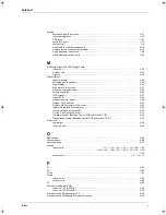
Index
v
3
4
5
1
locating
exploded views, indoor units ................................. . . . . . . . . . . . . . . . . . . . . . . . . . . . . . . . . . . .
k
5–17
functional diagrams ............................................... . . . . . . . . . . . . . . . . . . . . . . . . . . . . . . . . . . .
k
1–55
PCB layout ............................................................ . . . . . . . . . . . . . . . . . . . . . . . . . . . . . . . . . .
k
1–101
switch box layout................................................... . . . . . . . . . . . . . . . . . . . . . . . . . . . . . . . . . . .
k
1–73
thermistors ............................................................ . . . . . . . . . . . . . . . . . . . . . . . . . . . . . . . . . . . .
k
2–4
wired remote controller components ..................... . . . . . . . . . . . . . . . . . . . . . . . . . . . . . . . . . . .
k
4–10
wireless remote controller components................. . . . . . . . . . . . . . . . . . . . . . . . . . . . . . . . . . . .
k
4–12
wiring diagrams, indoor units ................................ . . . . . . . . . . . . . . . . . . . . . . . . . . . . . . . . . . .
k
1–85
wiring diagrams, outdoor units .............................. . . . . . . . . . . . . . . . . . . . . . . . . . . . . . . . . . . .
k
1–85
M
Malfunction Code and LED Display Table
Indoor Unit............................................................. . . . . . . . . . . . . . . . . . . . . . . . . . . . . . . . . . . .
k
3–34
Outdoor Unit.......................................................... . . . . . . . . . . . . . . . . . . . . . . . . . . . . . . . . . . .
k
3–35
System .................................................................. . . . . . . . . . . . . . . . . . . . . . . . . . . . . . . . . . . .
k
3–36
Malfunction of
capacity setting ..................................................... . . . . . . . . . . . . . . . . . . . . . . . . . . . . . . . . . . .
k
3–48
discharge pipe temerature .................................... . . . . . . . . . . . . . . . . . . . . . . . . . . . . . . . . . . .
k
3–65
drain system.......................................................... . . . . . . . . . . . . . . . . . . . . . . . . . . . . . . . . . . .
k
3–44
drain water level systemt....................................... . . . . . . . . . . . . . . . . . . . . . . . . . . . . . . . . . . .
k
3–41
electronic expansion valve .................................... . . . . . . . . . . . . . . . . . . . . . . . . . . . . . . . . . . .
k
3–63
field setting switch ................................................. . . . . . . . . . . . . . . . . . . . . . . . . . . . . . . . . . . .
k
3–94
HPS system .......................................................... . . . . . . . . . . . . . . . . . . . . . . . . . . . . . . . . . . .
k
3–67
indoor PCB............................................................ . . . . . . . . . . . . . . . . . . . . . . . . . . . . . . . . . . .
k
3–40
outdoor fan motor signal ....................................... . . . . . . . . . . . . . . . . . . . . . . . . . . . . . . . . . . .
k
3–68
Outdoor Unit Fan Motor ........................................ . . . . . . . . . . . . . . . . . . . . . . . . . . . . . . . . . . .
k
3–62
Radiator Fin Temperature Thermistor................... . . . . . . . . . . . . . . . . . . . . . . . . . . . . . . . . . . .
k
3–82
radiator fin temperature thermistor........................ . . . . . . . . . . . . . . . . . . . . . . . . . . . . . . . . . . .
k
3–82
remote controller air thermistor ............................. . . . . . . . . . . . . . . . . . . . . . . . . . . . . . . . . . . .
k
3–52
Suction Pipe Pressure Sensor .............................. . . . . . . . . . . . . . . . . . . . . . . . . . . . . . . . . . . .
k
3–70
thermistor system (Between Control PCB and Inverter PCB). . . . . . . . . . . . . . . . . . . . . . . . . . .
k
3–69
Transmission system (Between Control PCB and Inverter PCB) . . . . . . . . . . . . . . . . . . . . . . . .
k
3–78
Motor lock
compressor ........................................................... . . . . . . . . . . . . . . . . . . . . . . . . . . . . . . . . . . .
k
3–60
indoor unit fan ....................................................... . . . . . . . . . . . . . . . . . . . . . . . . . . . . . . . . . . .
k
3–46
O
Open Phase . . . . . . . . . . . . . . . . . . . . . . . . . . . . . . . . . .. . . . . . . . . . . . . . . . . . . . . . . . . . . . . . . . . . . .
k
3–80
operation data . . . . . . . . . . . . . . . . . . . . . . . . . . . . . . . . .. . . . . . . . . . . . . . . . . . . . . . . . . . . . . . . . . . . .
k
4–38
operation range . . . . . . . . . . . . . . . . . . . . . . . . . . . . . . . .. . . . . . . . . . . . . . . . . . . . . . . . . . . . . . . . . . . .
k
4–37
outlook
indoor units . . . . . . . . . . . . . . . . . . . . . . . . . . . . . . . .
k
1–11
,
1–12
,
1–14
,
1–16
,
1–18
,
1–20
,
1–22
,
. . . . . . . . . . . . . . . . . . . . . . . . . . . . . . . . . . . . . . 1–24
,
1–26
,
1–28
,
1–30
,
1–32
,
1–34
,
1–36
,
1–38
,
. . . . . . . . . . . . . . . . . . . . . . . . . . . . . . . . . . . . . . . . . . . . . . . . . . . . . . . . . . . . . . . . . . . . . . . . . . . . 1–40
outdoor units ......................................................... . . . . . . . . . . . . . . . . . . . . . . . . . . .
k
1–3
,
1–4
,
1–6
P
P1 . . . . . . . . . . . . . . . . . . . . . . . . . . . . . . . . . . . . . . . . . .. . . . . . . . . . . . . . . . . . . . . . . . . . . . . . . . . . . .
k
3–80
P4 . . . . . . . . . . . . . . . . . . . . . . . . . . . . . . . . . . . . . . . . . .. . . . . . . . . . . . . . . . . . . . . . . . . . . . . . . . . . . .
k
3–82
PCBs . . . . . . . . . . . . . . . . . . . . . . . . . . . . . . . . . . . . . . . .. . . . . . . . . . . . . . . . . . . . . . . . . . . . . . . . . . .
k
1–101
Piping
indoor units............................................................ . . . . . . . . . . . . . . . . . . . . . . . . . . . . . . . . . . .
k
1–62
outdoor units ......................................................... . . . . . . . . . . . . . . . . . . . . . . . . . . . . . . . . . . .
k
1–56
PJ . . . . . . . . . . . . . . . . . . . . . . . . . . . . . . . . . . . . . . . . . .. . . . . . . . . . . . . . . . . . . . . . . . . . . . . . . . . . . .
k
3–84
Printed Circuit Board (PCB)
Indoor Unit PCB (FFQ-B) ...................................... . . . . . . . . . . . . . . . . . . . . . . . . . . . . . . . . . . .
k
5–60
Indoor Unit PCB (FHQ-B)...................................... . . . . . . . . . . . . . . . . . . . . . . . . . . . . . . . . . . .
k
5–70
Procedure of Self-Diagnosis by LED . . . . . . . . . . . . . . . .. . . . . . . . . . . . . . . . . . . . . . . . . . . . . . . . . . . .
k
3–32
Procedure of Self-Diagnosis by Remote Controller. . . . .. . . . . . . . . . . . . . . . . . . . . . . . . . . . . . . . . . . .
k
3–24
RZQ - Final.book Page v Wednesday, September 8, 2004 8:40 AM
Summary of Contents for RZQ71~125B7V3B
Page 1: ...Service Manual ESIE04 01 RZQ71 125B7V3B Sky Air Inverter R 410A B series ...
Page 2: ......
Page 24: ...ESIE04 01 1 2 Part 1 System Outline 3 1 1 5 ...
Page 32: ...General Outline Outdoor Units ESIE04 01 1 10 Part 1 System Outline 3 1 1 4 5 ...
Page 64: ...General Outline Indoor Units ESIE04 01 1 42 Part 1 System Outline 3 1 1 4 5 ...
Page 76: ...Specifications ESIE04 01 1 54 Part 1 System Outline 3 1 1 4 5 ...
Page 92: ...Functional Diagrams ESIE04 01 1 70 Part 1 System Outline 3 1 1 4 5 ...
Page 94: ...ESIE04 01 1 72 Part 1 System Outline ...
Page 122: ...Wiring Diagrams ESIE04 01 1 100 Part 1 System Outline 3 1 1 4 5 ...
Page 140: ...ESIE04 01 2 2 Part 2 Functional Description 3 1 2 5 ...
Page 162: ...General Functionality ESIE04 01 2 24 Part 2 Functional Description 3 1 2 4 5 ...
Page 200: ...Outdoor Unit Functional Concept ESIE04 01 2 62 Part 2 Functional Description 3 1 2 4 5 ...
Page 202: ...ESIE04 01 3 2 Part 3 Troubleshooting 3 1 3 5 ...
Page 288: ...Error Codes Outdoor Units ESIE04 01 3 88 Part 3 Troubleshooting 3 1 3 4 5 ...
Page 312: ...Additional Checks for Troubleshooting ESIE04 01 3 112 Part 3 Troubleshooting 3 1 3 4 5 ...
Page 314: ...ESIE04 01 4 2 Part 4 Commissioning and Test Run 3 1 4 5 ...
Page 356: ...ESIE04 01 5 2 Part 5 Disassembly and Maintenance 3 1 5 ...
Page 484: ...ESIE04 01 viii Index 3 1 4 5 ...


