ESIE04-01
vi
Index
3
1
4
5
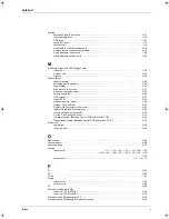
Pump down operation . . . . . . . . . . . . . . . . . . . . . . . . . . .. . . . . . . . . . . . . . . . . . . . . . . . . . . . . . . . . . . .
k
2–17
Pump down residual operation . . . . . . . . . . . . . . . . . . . .. . . . . . . . . . . . . . . . . . . . . . . . . . . . . . . . . . . .
k
2–16
R
R3T
resistance conversion table ................................... . . . . . . . . . . . . . . . . . . . . . . . . . . . . . . . . . .
k
3–104
Radiation Fin Temperature Increased . . . . . . . . . . . . . . .. . . . . . . . . . . . . . . . . . . . . . . . . . . . . . . . . . . .
k
3–71
Receiver Section . . . . . . . . . . . . . . . . . . . . . . . . . . . . . . .. . . . . . . . . . . . . . . . . . . . . . . . . . . . . . . . . . . .
k
5–64
Refrigerant Cylinders . . . . . . . . . . . . . . . . . . . . . . . . . . . .. . . . . . . . . . . . . . . . . . . . . . . . . . . . . . . . . . . . .
k
i–vi
Refrigerant R410A . . . . . . . . . . . . . . . . . . . . . . . . . . . . . .. . . . . . . . . . . . . . . . . . . . . . . . . . . . . . . . . . . . .
k
i–iv
regulating functions
expansion valve..................................................... . . . . . . . . . . . . . . . . . . . . . . . . . . . . . . . . . . .
k
2–55
frequency............................................................... . . . . . . . . . . . . . . . . . . . . . . . . . . . . . . . . . . .
k
2–39
remote controller
multiple setting....................................................... . . . . . . . . . . . . . . . . . . . . . . . . . . . . . . . . . . . .
k
4–8
setting address for receiver of wireless remote controller . . . . . . . . . . . . . . . . . . . . . . . . . . . . . . .
k
4–5
setting address for wireless remote controller ...... . . . . . . . . . . . . . . . . . . . . . . . . . . . . . . . . . . . .
k
4–6
thermostat, using conditions.................................. . . . . . . . . . . . . . . . . . . . . . . . . . . . . . . . . . . .
k
2–12
Remote Controller Display Malfunction Code and Contents. . . . . . . . . . . . . . . . . . . . . . . . . . . . . . . . . .
k
3–30
S
safety devices
indoor..................................................................... . . . . . . . . . . . . . . . . . . . . . . . . . . . . . . . . . . .
k
3–38
outdoor .................................................................. . . . . . . . . . . . . . . . . . . . . . . . . . . . . . . . . . . .
k
3–37
Self-Diagnosis by Wired Remote Controller . . . . . . . . . .. . . . . . . . . . . . . . . . . . . . . . . . . . . . . . . . . . . .
k
3–25
service space
outdoor units.......................................................... . . . . . . . . . . . . . . . . . . . . . . . . . . . . . . . . . . . .
k
1–3
Service Tools . . . . . . . . . . . . . . . . . . . . . . . . . . . . . . . . . .. . . . . . . . . . . . . . . . . . . . . . . . . . . . . . . . . . . . .
k
i–vii
setting
address for receiver of wireless remote controller. . . . . . . . . . . . . . . . . . . . . . . . . . . . . . . . . . . . .
k
4–5
address for wireless remote controller................... . . . . . . . . . . . . . . . . . . . . . . . . . . . . . . . . . . . .
k
4–6
ceiling height.......................................................... . . . . . . . . . . . . . . . . . . . . . . . . . . . . . . . . . . .
k
4–15
centralized group No. ............................................ . . . . . . . . . . . . . . . . . . . . . . . . . . . . . . . . . . .
k
4–18
field settings, wired remote controller .................... . . . . . . . . . . . . . . . . . . . . . . . . . . . . . . . . . . .
k
4–11
field settings, wireless remote controller................ . . . . . . . . . . . . . . . . . . . . . . . . . . . . . . . . . . .
k
4–12
filter counter........................................................... . . . . . . . . . . . . . . . . . . . . . . . . . . . . . . . . . . .
k
4–16
low humidity application......................................... . . . . . . . . . . . . . . . . . . . . . . . . . . . . . . . . . . .
k
4–30
MAIN/SUB when using two remote controllers...... . . . . . . . . . . . . . . . . . . . . . . . . . . . . . . . . . . .
k
4–17
settings
BS.......................................................................... . . . . . . . . . . . . . . . . . . . . . . . . . . . . . . . . . . .
k
4–24
changing maintenance mode ................................ . . . . . . . . . . . . . . . . . . . . . . . . . . . . . . . . . . .
k
4–21
DIP switches.......................................................... . . . . . . . . . . . . . . . . . . . . . . . . . . . . . . . . . . .
k
4–24
factory overview indoor units ................................. . . . . . . . . . . . . . . . . . . . . . . . . . . . . . . . . . . .
k
4–14
factory overview outdoor units............................... . . . . . . . . . . . . . . . . . . . . . . . . . . . . . . . . . . .
k
4–25
field overview indoor units ..................................... . . . . . . . . . . . . . . . . . . . . . . . . . . . . . . . . . . .
k
4–13
field overview outdoor units ................................... . . . . . . . . . . . . . . . . . . . . . . . . . . . . . . . . . . .
k
4–23
jumpers overview................................................... . . . . . . . . . . . . . . . . . . . . . . . . . . . . . . . . . . .
k
4–23
maintenance mode ................................................ . . . . . . . . . . . . . . . . . . . . . . . . . . . . . . . . . . .
k
4–22
possible system settings........................................ . . . . . . . . . . . . . . . . . . . . . . . . . . . . . . . . . . .
k
4–21
remote controller.................................................... . . . . . . . . . . . . . . . . . . . . . . . . . . . . . . . . . . .
k
4–23
silent operation . . . . . . . . . . . . . . . . . . . . . . . . . . . . . . . .. . . . . . . . . . . . . . . . . . . . . . . . . . . . . . . . . . . .
k
4–26
simulated operation function . . . . . . . . . . . . . . . . . . . . . .. . . . . . . . . . . . . . . . . . . . . . . . . . . . . . . . . . . . .
k
2–9
specifications . . . . . . . . . . . . . . . . . . . . . . . . . . . . . . . . . .. . . . . . . . . . . . . . . . . . . . . . . . . . . . . . . . . . . .
k
1–43
Stall Prevention (Time Lag) . . . . . . . . . . . . . . . . . . . . . . .. . . . . . . . . . . . . . . . . . . . . . . . . . . . . . . . . . . .
k
3–76
Standard Conditions . . . . . . . . . . . . . . . . . . . . . . . . . . . .. . . . . . . . . . . . . . . . . . . . . . . . . . . . . . . . . . . .
k
4–39
Suction Grille . . . . . . . . . . . . . . . . . . . . . . . . . . . . . . . . . . . . . . . . . . . . . . . . . . . . . . . . . .
k
5–31
,
5–68
,
5–84
Swing Motor. . . . . . . . . . . . . . . . . . . . . . . . . . . . . . . . . . . . . . . . . . . . . . . . . . . . .
k
5–39
,
5–81
,
5–95
,
5–108
Switch Box . . . . . . . . . . . . . . . . . . . . . . . . . . . . . . . . . . . .. . . . . . . . . . . . . . . . . . . . . . . . . . . . . . . . . . . .
k
5–41
switch boxes . . . . . . . . . . . . . . . . . . . . . . . . . . . . . . . . . .. . . . . . . . . . . . . . . . . . . . . . . . . . . . . . . . . . . .
k
1–73
RZQ - Final.book Page vi Wednesday, September 8, 2004 8:40 AM
Summary of Contents for RZQ71~125B7V3B
Page 1: ...Service Manual ESIE04 01 RZQ71 125B7V3B Sky Air Inverter R 410A B series ...
Page 2: ......
Page 24: ...ESIE04 01 1 2 Part 1 System Outline 3 1 1 5 ...
Page 32: ...General Outline Outdoor Units ESIE04 01 1 10 Part 1 System Outline 3 1 1 4 5 ...
Page 64: ...General Outline Indoor Units ESIE04 01 1 42 Part 1 System Outline 3 1 1 4 5 ...
Page 76: ...Specifications ESIE04 01 1 54 Part 1 System Outline 3 1 1 4 5 ...
Page 92: ...Functional Diagrams ESIE04 01 1 70 Part 1 System Outline 3 1 1 4 5 ...
Page 94: ...ESIE04 01 1 72 Part 1 System Outline ...
Page 122: ...Wiring Diagrams ESIE04 01 1 100 Part 1 System Outline 3 1 1 4 5 ...
Page 140: ...ESIE04 01 2 2 Part 2 Functional Description 3 1 2 5 ...
Page 162: ...General Functionality ESIE04 01 2 24 Part 2 Functional Description 3 1 2 4 5 ...
Page 200: ...Outdoor Unit Functional Concept ESIE04 01 2 62 Part 2 Functional Description 3 1 2 4 5 ...
Page 202: ...ESIE04 01 3 2 Part 3 Troubleshooting 3 1 3 5 ...
Page 288: ...Error Codes Outdoor Units ESIE04 01 3 88 Part 3 Troubleshooting 3 1 3 4 5 ...
Page 312: ...Additional Checks for Troubleshooting ESIE04 01 3 112 Part 3 Troubleshooting 3 1 3 4 5 ...
Page 314: ...ESIE04 01 4 2 Part 4 Commissioning and Test Run 3 1 4 5 ...
Page 356: ...ESIE04 01 5 2 Part 5 Disassembly and Maintenance 3 1 5 ...
Page 484: ...ESIE04 01 viii Index 3 1 4 5 ...


