General Outline: Indoor Units
ESIE04-01
1–30
Part 1 – System Outline
3
11
4
5
2.11
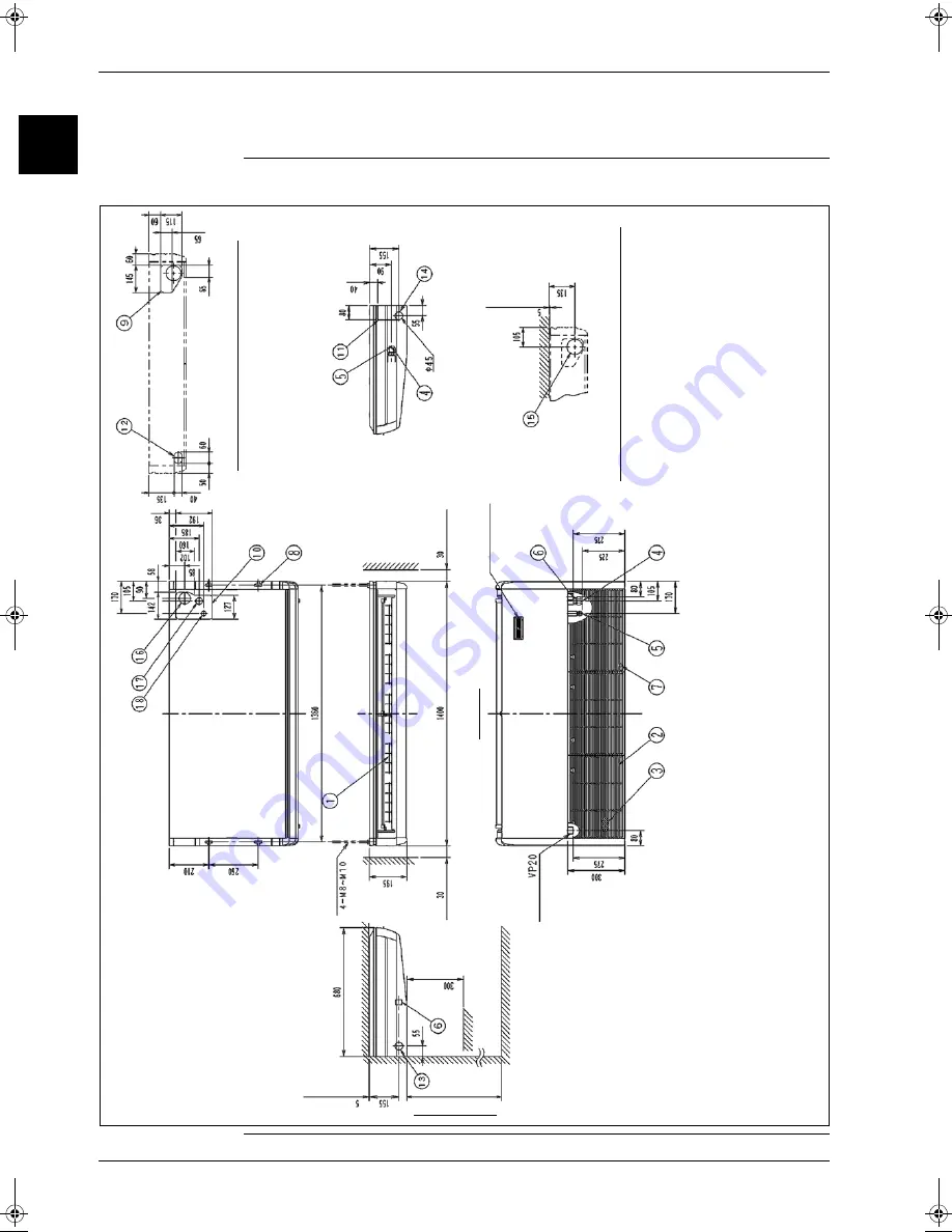
FHQ100BUV1B
Outlook and
dimensions
The illustration below shows the outlook and the dimensions of the unit (mm).
Posit
ion
slit
hole f
o
r
ta
k
ing
out
in
pi
ping
back
or more
(S
e
rvice S
pace
)
B
rand name
pl
ate
(N
o
te 2)
D
rai
n pi
pe
conne
cti
o
n
(F
or l
e
ft
pi
pi
ng)
The
f
ront
Fl
oo
r si
de
Obstacle
(Requ
ired sp
ace)
or mo
re
For hei
ght i
nstal
la
tion
From t
he floo
r side 2
500 or mo
re
(Requ
ired sp
ace)
(V
ie
w
f
rom t
he f
ront
)
(H
an
gi
ng po
si
ti
on)
(Ha
nging p
osi
tion)
H
a
n
g
ing bo
lt
(Requ
ired sp
ace)
P
o
sit
ion:
Hol
e
of
wall
fo
r t
a
k
ing out
in
p
iping back
(V
iew f
rom
t
he f
ront
)
or m
o
re
(S
e
rvice S
pace
)
NOT
E
S
:
1.
Locat
ion of
unit
’s
Nam
e
plat
e:
Bot
tom
of
f
an
housing ins
ide
t
he s
u
ct
ion
grill
.
2.
In
cas
e
of
using wi
re
le
ss rem
o
te
cont
roller,
t
h
is
posit
ion wil
l be
a signal receiver.
Ref
e
r t
o
t
he
drawing
of
wi
re
le
ss remot
e
cont
ro
ller
in
de
ta
il.
3.
T
he rem
o
te
cont
rol
c
ode
is t
h
e
st
andard
<about
3m out
s
ide
the
m
a
chine> at
ta
ched.
(0
.5
m
m
² x
2
w
ic
k
s
x
O
.D
.
ø
5
.4
)
(I
t is
not
at
ta
c
hed t
o
V
R
V.
)
RZQ - Final.book Page 30 Wednesday, September 8, 2004 8:40 AM
Summary of Contents for RZQ71~125B7V3B
Page 1: ...Service Manual ESIE04 01 RZQ71 125B7V3B Sky Air Inverter R 410A B series ...
Page 2: ......
Page 24: ...ESIE04 01 1 2 Part 1 System Outline 3 1 1 5 ...
Page 32: ...General Outline Outdoor Units ESIE04 01 1 10 Part 1 System Outline 3 1 1 4 5 ...
Page 64: ...General Outline Indoor Units ESIE04 01 1 42 Part 1 System Outline 3 1 1 4 5 ...
Page 76: ...Specifications ESIE04 01 1 54 Part 1 System Outline 3 1 1 4 5 ...
Page 92: ...Functional Diagrams ESIE04 01 1 70 Part 1 System Outline 3 1 1 4 5 ...
Page 94: ...ESIE04 01 1 72 Part 1 System Outline ...
Page 122: ...Wiring Diagrams ESIE04 01 1 100 Part 1 System Outline 3 1 1 4 5 ...
Page 140: ...ESIE04 01 2 2 Part 2 Functional Description 3 1 2 5 ...
Page 162: ...General Functionality ESIE04 01 2 24 Part 2 Functional Description 3 1 2 4 5 ...
Page 200: ...Outdoor Unit Functional Concept ESIE04 01 2 62 Part 2 Functional Description 3 1 2 4 5 ...
Page 202: ...ESIE04 01 3 2 Part 3 Troubleshooting 3 1 3 5 ...
Page 288: ...Error Codes Outdoor Units ESIE04 01 3 88 Part 3 Troubleshooting 3 1 3 4 5 ...
Page 312: ...Additional Checks for Troubleshooting ESIE04 01 3 112 Part 3 Troubleshooting 3 1 3 4 5 ...
Page 314: ...ESIE04 01 4 2 Part 4 Commissioning and Test Run 3 1 4 5 ...
Page 356: ...ESIE04 01 5 2 Part 5 Disassembly and Maintenance 3 1 5 ...
Page 484: ...ESIE04 01 viii Index 3 1 4 5 ...


