6 Installation
Installer reference guide
14
RZQG71~Y1 + RZQSG100~Y1
Split system air conditioners
4P385522-1A – 2016.10
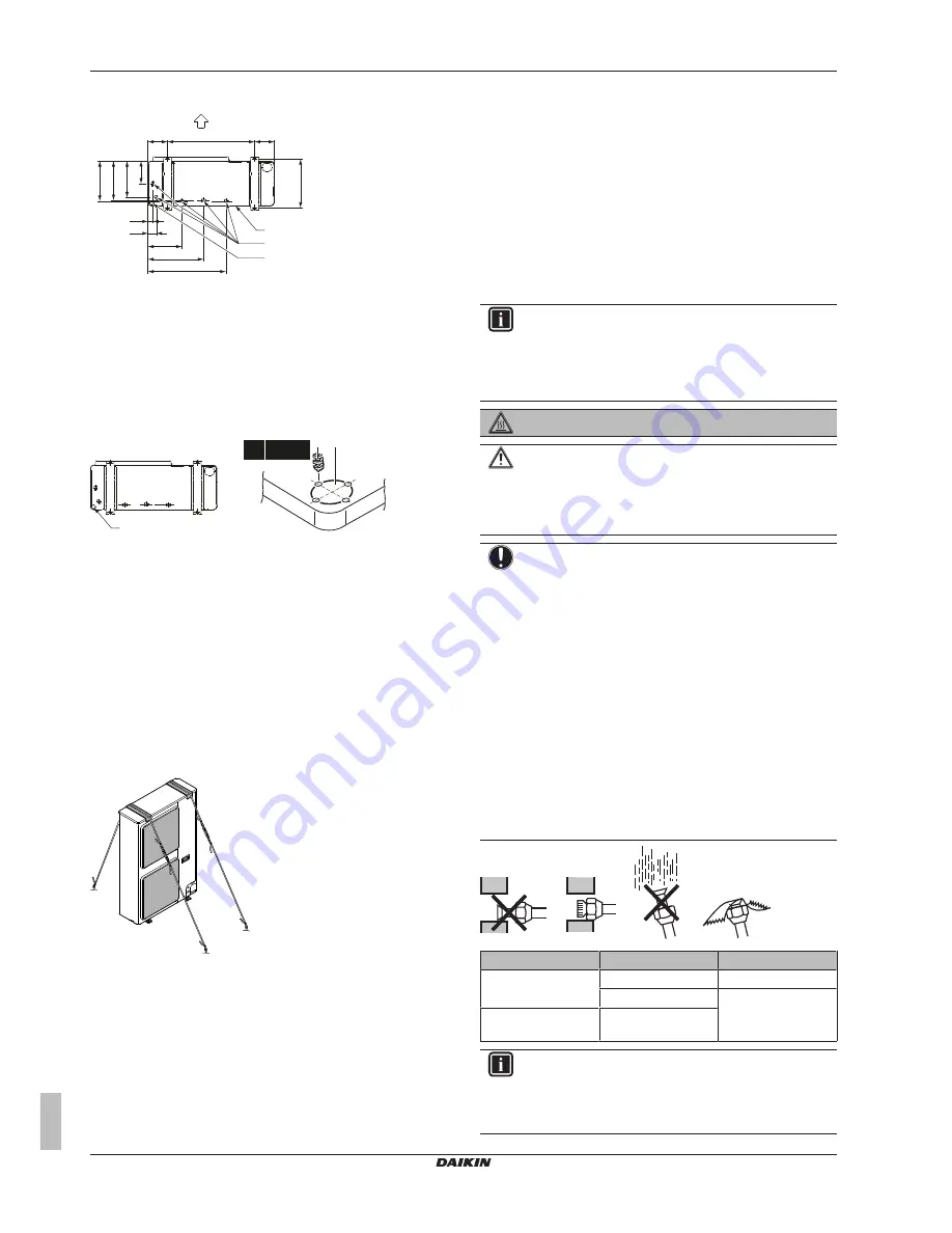
Drain holes (dimensions in mm)
A
B
B
C
D
E
160
160
620
36
61
262
416
595
285
279
260
161
(345~355)
A
Discharge side
B
Distance between anchor points
C
Bottom frame
D
Drain holes
E
Knockout hole for snow
Snow
In regions with snowfall, snow might build up and freeze between the
heat exchanger and the external plate. This might decrease the
operating efficiency. To prevent this:
1
Drill (a, 4×) and remove the knockout hole (b).
b
a b
4× Ø6 mm
2
Remove the burrs, and paint the edges and areas around the
edges using repair paint to prevent rusting.
6.3.6
To prevent the outdoor unit from falling
over
In case the unit is installed in places where strong wind can tilt the
unit, take following measure:
1
Prepare 2 cables as indicated in the following illustration (field
supply).
2
Place the 2 cables over the outdoor unit.
3
Insert a rubber sheet between the cables and the outdoor unit
to prevent the cable from scratching the paint (field supply).
4
Attach the cable’s ends. Tighten those ends.
6.4
Connecting the refrigerant piping
6.4.1
About connecting the refrigerant piping
Before connecting the refrigerant piping
Make sure the outdoor and indoor unit are mounted.
Typical workflow
Connecting the refrigerant piping involves:
▪ Connecting the refrigerant piping to the outdoor unit
▪ Connecting the refrigerant piping to the indoor unit
▪ Installing oil traps
▪ Insulating the refrigerant piping
▪ Keeping in mind the guidelines for:
▪ Pipe bending
▪ Flaring pipe ends
▪ Brazing
▪ Using the stop valves
6.4.2
Precautions when connecting the
refrigerant piping
INFORMATION
Also read the precautions and requirements in the
following chapters:
▪ General safety precautions
▪ Preparation
DANGER: RISK OF BURNING
CAUTION
▪ Do NOT use mineral oil on flared part.
▪ NEVER install a drier to this R410A unit to guarantee
its lifetime. The drying material may dissolve and
damage the system.
NOTICE
Take the following precautions on refrigerant piping into
account:
▪ Avoid anything but the designated refrigerant to get
mixed into the refrigerant cycle (e.g. air).
▪ Only use R410A when adding refrigerant.
▪ Only use installation tools (e.g. manifold gauge set) that
are exclusively used for R410A installations to
withstand the pressure and to prevent foreign materials
(e.g. mineral oils and moisture) from mixing into the
system.
▪ Install the piping so that the flare is NOT subjected to
mechanical stress
▪ Protect the piping as described in the following table to
prevent dirt, liquid or dust from entering the piping.
▪ Use caution when passing copper tubes through walls
(see figure below).
Unit
Installation period
Protection method
Outdoor unit
>1 month
Pinch the pipe
<1 month
Pinch or tape the pipe
Indoor unit
Regardless of the
period
INFORMATION
Do NOT open the refrigerant stop valve before checking
the refrigerant piping. When you need to charge additional
refrigerant it is recommended to open the refrigerant stop
valve after charging.


