background image

6 Installation

Installer reference guide

18

RZQG71~Y1 + RZQSG100~Y1

Split system air conditioners

4P385522-1A – 2016.10

NOTICE

Use  this  vacuum  pump  for  R410A  exclusively.  Using  the
same  pump  for  other  refrigerants  may  damage  the  pump
and the unit.

NOTICE

▪ Connect  the  vacuum  pump  to 

both

  the  service  port  of

the  gas  stop  valve  and  the  service  port  of  the  liquid
stop valve to increase efficiency.

▪ Make sure that the gas stop valve and liquid stop valve

are  firmly  closed  before  performing  the  leak  test  or
vacuum drying.

6.5.3

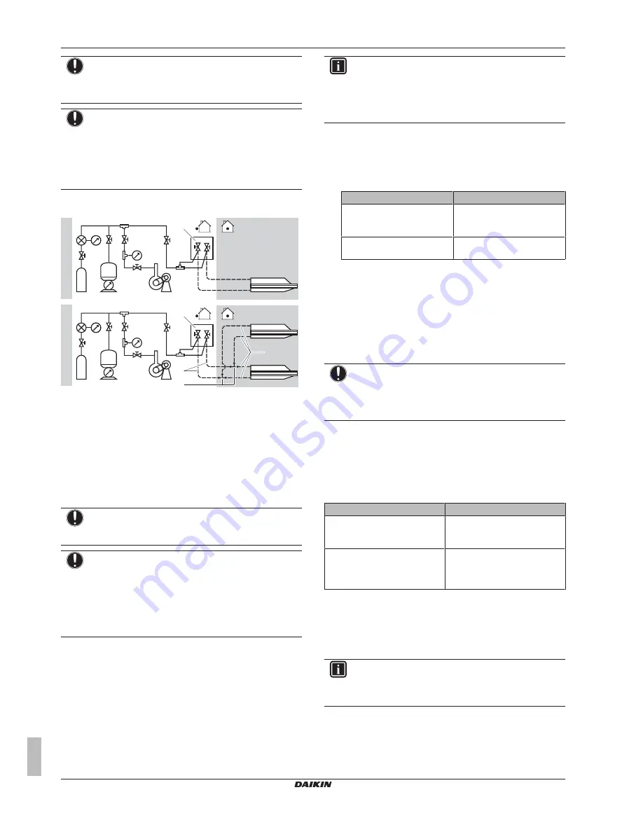
Checking refrigerant piping: Setup

a

c

f

c

f

b

d

e h

g

i

a

b

A

B

d

e

R410A

R410A

A

Setup in case of pair

B

Setup in case of twin

a

Pressure gauge

b

Nitrogen

c

Refrigerant

d

Weighing machine

e

Vacuum pump

f

Stop valve

g

Main piping

h

Refrigerant branch kit

i

Branch piping

6.5.4

To check for leaks

NOTICE

Do NOT exceed the unit's maximum working pressure (see
"PS High" on the unit name plate).

NOTICE

Make  sure  to  use  a  recommended  bubble  test  solution
from  your  wholesaler.  Do  not  use  soap  water,  which  may
cause cracking of flare nuts (soap water may contain salt,
which  absorbs  moisture  that  will  freeze  when  the  piping
gets  cold),  and/or  lead  to  corrosion  of  flared  joints  (soap
water  may  contain  ammonia  which  causes  a  corrosive
effect between the brass flare nut and the copper flare).

1

Charge the system with nitrogen gas up to a gauge pressure of
at  least  200  kPa  (2  bar).  It  is  recommended  to  pressurize  to
3000 kPa (30 bar) in order to detect small leaks.

2

Check  for  leaks  by  applying  the  bubble  test  solution  to  all
connections.

3

Discharge all nitrogen gas.

INFORMATION

After opening the stop valve, it is possible that the pressure
in the refrigerant piping does NOT increase. This might be
caused  by  e.g.  the  closed  state  of  the  expansion  valve  in
the outdoor unit circuit, but does NOT present any problem
for correct operation of the unit.

6.5.5

To perform vacuum drying

1

Vacuum the system until the pressure on the manifold indicates
−0.1 MPa (−1 bar).

2

Leave as is for 4-5 minutes and check the pressure:

If the pressure…

Then…

Does not change

There is no moisture in the
system. This procedure is
finished.

Increases

There is moisture in the
system. Go to the next step.

3

Evacuate  for  at  least  2  hours  to  a  pressure  on  the  manifold  of
−0.1 MPa (−1 bar).

4

After  turning  OFF  the  pump,  check  the  pressure  for  at  least
1 hour.

5

If you do NOT reach the target vacuum or cannot maintain the
vacuum for 1 hour, do the following:

▪ Check for leaks again.
▪ Perform vacuum drying again.

NOTICE

Make  sure  to  open  the  stop  valves  after  installing  the
refrigerant  piping  and  performing  vacuum  drying.  Running
the  system  with  the  stop  valves  closed  may  break  the
compressor.

6.6

Charging refrigerant

6.6.1

About charging refrigerant

The  outdoor  unit  is  factory  charged  with  refrigerant,  but  in  some
cases the following might be necessary:

What

When

Charging additional refrigerant

When the total liquid piping
length is more than specified
(see later).

Completely recharging refrigerant

Example:

▪ When relocating the system.

▪ After a leak.

For RZQG only: When piping length is <5 m, a complete recharge of
the unit is required.

Charging additional refrigerant

Before  charging  additional  refrigerant,  make  sure  the  outdoor  unit's

external

 refrigerant piping is checked (leak test, vacuum drying).

INFORMATION

Depending on the units and/or the installation conditions, it
might be necessary to connect electrical wiring before you
can charge refrigerant.

Typical  workflow  –  Charging  additional  refrigerant  typically  consists
of the following stages:

1 Determining if and how much you have to charge additionally.

2 If necessary, charging additional refrigerant.

Summary of Contents for RZQG71L9V1B

Page 1: ...rs English Installer reference guide Split system air conditioners RZQG71L9V1B RZQG100L9V1B RZQG125L9V1B RZQG140L9V1B RZQG71L8Y1B RZQG100L8Y1B RZQG125L8Y1B RZQG140L7Y1B RZQSG100L9V1B RZQSG125L9V1B RZQ...

Page 2: ...ng to the outdoor unit 16 6 4 9 To determine if oil traps are required 17 6 5 Checking the refrigerant piping 17 6 5 1 About checking the refrigerant piping 17 6 5 2 Precautions when checking the refr...

Page 3: ...F BURNING Do NOT touch the refrigerant piping water piping or internal parts during and immediately after operation It could be too hot or too cold Give it time to return to normal temperature If you...

Page 4: ...ion WARNING Make sure there is no oxygen in the system Refrigerant may only be charged after performing the leak test and the vacuum drying In case re charge is required refer to the nameplate of the...

Page 5: ...esistant to high frequency electric noise to avoid unnecessary opening of the earth leakage protector NOTICE Precautions when laying power wiring Do not connect wiring of different thicknesses to the...

Page 6: ...allation What to do and know to install the system Commissioning What to do and know to commission the system after it is installed Hand over to the user What to give and explain to the user Maintenan...

Page 7: ...L7 in combination with RZQG_V1 you also have to install the demand adaptor kit For installation instructions see the installation manual of the bottom plate heater Demand adaptor kit Can be used for t...

Page 8: ...eaker 1 5 height of outdoor unit Mind the service space requirements when installing the windbreaker a b c d c d a Sea wind b Building c Outdoor unit d Windbreaker Strong winds 18 km h blowing against...

Page 9: ...oil checking reference card This is available from your dealer 1 Put some residual oil from the piping on a piece of white paper 2 Compare the colours If the oil colour is Then Identical to or darker...

Page 10: ...iquid piping 9 5 mm Gas piping 15 9 mm L1 pair twin triple double twin Model New a Existing b L1 liquid piping L1 gas piping RZQG71 Size down 6 4 mm 12 7 mm Standard 9 5 mm 15 9 mm Size up 12 7 mm RZQ...

Page 11: ...m b 25 m 35 m b 3 Maximum allowable piping length Pair N A Twin L1 L2 L3 Limit 60 m 75 m 50 m Triple L1 L2 L3 L4 Limit 75 m 50 m Double twin L1 L2 L3 L4 L5 L6 L7 Limit 75 m 50 m 4 Maximum branch pipi...

Page 12: ...because this unit is equipped with an inverter A phase advancing capacitor will reduce performance and may cause accidents WARNING All wiring must be performed by an authorized electrician and must co...

Page 13: ...0 350 3 4 5 3 5 5 4 M12 a a Make sure not to cover the drain holes INFORMATION The recommended height of the upper protruding part of the bolts is 20 mm 20 NOTICE Fix the outdoor unit to the foundatio...

Page 14: ...ting the refrigerant piping to the indoor unit Installing oil traps Insulating the refrigerant piping Keeping in mind the guidelines for Pipe bending Flaring pipe ends Brazing Using the stop valves 6...

Page 15: ...stration A Flare tool for R410A clutch type Conventional flare tool Clutch type Ridgid type Wing nut type Imperial type A 0 0 5 mm 1 0 1 5 mm 1 5 2 0 mm 5 Check that the flaring is properly made a b c...

Page 16: ...tem cap is sealed where indicated with the arrow Do NOT damage it After handling the stop valve tighten the stem cap and check for refrigerant leaks Item Tightening torque N m Stem cap liquid side 13...

Page 17: ...is might cause liquid compression or deterioration of oil return Oil traps in the rising gas piping can prevent this If Then The indoor unit is installed higher than the outdoor unit Install an oil tr...

Page 18: ...be caused by e g the closed state of the expansion valve in the outdoor unit circuit but does NOT present any problem for correct operation of the unit 6 5 5 To perform vacuum drying 1 Vacuum the sys...

Page 19: ...nents with specific functions e g valves The refrigerant circuit therefore features additional service ports for vacuuming pressure relief or pressurizing the circuit In case it is required to perform...

Page 20: ...ize up G2 m Total length of 6 4 mm liquid piping 2 Determine R1 and R2 If Then G1 30 m a Use the table below to determine R1 length G1 30 m a and R2 length G2 If Then G1 30 m a and G1 G2 30 m a R1 0 0...

Page 21: ...see unit name plate c Additional refrigerant amount charged d Total refrigerant charge e Greenhouse gas emissions of the total refrigerant charge expressed as tonnes CO2 equivalent f GWP Global warmin...

Page 22: ...d conductor wire with round crimp style terminal c b b a c a B B a Terminal b Screw c Flat washer Tightening torques Item Tightening torque N m M4 X1M 1 2 1 8 M4 earth 1 2 1 4 M5 X1M 2 0 3 0 M5 earth...

Page 23: ...ies a b a b a b 2 3 1 a Power supply cable b Interconnection cable Connecting to the frame When cables are routed from the unit a protection sleeve for the conduits PG insertions can be inserted at th...

Page 24: ...rate the unit without thermistors and or pressure sensors switches Burning of the compressor might result NOTICE Do NOT operate the unit until the refrigerant piping is complete when operated this way...

Page 25: ...the unit to cooling operation mode 2 Start the test run Action Result 1 Go to the home menu Cool Set to 28 C 2 Press at least 4 seconds The Service Settings menu is displayed 3 Select Test Operation...

Page 26: ...he user what to do in relation to maintaining the unit 9 Maintenance and service NOTICE Maintenance must be done by an authorised installer or service agent We recommend to do maintenance at least onc...

Page 27: ...ANGER RISK OF EXPLOSION Pump down Refrigerant leakage If you want to pump down the system and there is a leakage in the refrigerant circuit Do NOT use the unit s automatic pump down function with whic...

Page 28: ...A B C D E HB HU HD B 100 A B C 100 100 100 B E 100 1000 500 A B C E 150 150 150 1000 500 D 500 D E 1000 500 500 500 500 B D 100 100 B D E HB HD HB HD HB HU 250 750 1000 500 HU HB HU 250 1000 1000 500...

Page 29: ...red to install a roof but seal the gap between the upper and lower units to prevent discharged air from flowing back to the suction side through the bottom of the unit 12 2 Piping diagram Outdoor unit...

Page 30: ...1U F2U Fuse F6U Fuse T 3 15 A 250 V F7U F8U Fuse F 1 0 A 250 V F1U F8U RZQG100 140_V1 RZQSG125 140_V1 F1U F4U Fuse F6U Fuse T 5 0 A 250 V F7U F8U Fuse F 1 0 A 250 V F1U F8U RZQ S G_Y1 F1U F2U Fuse 31...

Page 31: ...ed company which can perform or coordinate the required service to the product Installation manual Instruction manual specified for a certain product or application explaining how to install configure...

Page 32: ...4P385522 1A 2016 10 Copyright 2014 Daikin...

Reviews: