9 Maintenance and service
Installer and user reference guide
44
SERHQ020~0 SEHVX20~64BAW
Split packaged air-cooled water chiller
4P508020-1B – 2018.04
WARNING
▪ Before carrying out any maintenance or repair activity,
ALWAYS switch off the circuit breaker on the supply
panel, remove the fuses or open the protection devices
of the unit.
▪ Do NOT touch live parts for 10 minutes after the power
supply is turned off because of high voltage risk.
▪ Please note that some sections of the electric
component box are hot.
▪ Make sure you do NOT touch a conductive section.
▪ Do NOT rinse the unit. This may cause electric shocks
or fire.
9.2.1
To prevent electrical hazards
When performing service to inverter equipment:
1
Do NOT open the electrical component box cover for 10
minutes after the power supply is turned off.
2
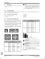
Measure the voltage between terminals on the terminal block
for power supply with a tester and confirm that the power supply
is shut off. In addition, measure points as shown in the figure,
with a tester and confirm that the voltage of the capacitor in the
main circuit is less than 50 V DC.
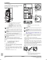
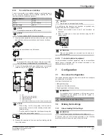
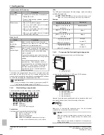
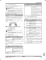
A1P
A3P
A2P
TP1 TP2
3
To prevent damaging the PCB, touch a non-coated metal part
to eliminate static electricity before pulling out or plugging in
connectors.
4
Pull out junction connectors X1A, X2A (X3A, X4A) for the fan
motors in the outdoor unit before starting service operation on
the inverter equipment. Be careful not to touch the live parts. (If
a fan rotates due to strong wind, it may store electricity in the
capacitor or in the main circuit and cause electric shock.)
5
After the service is finished, plug the junction connector back in.
Otherwise the malfunction code
will be displayed on the
user interface and normal operation will not be performed.
For details refer to the wiring diagram labelled on the back of the
electrical component box cover.
9.3
About service mode operation
When the vacuuming/recovery mode is used, check very carefully
what should be vacuumed/recovered before starting.
9.3.1
To use vacuum mode
1
With the unit at a standstill and setting mode 2 active, set the
required field setting (refrigerant recovery operation/vacuuming
operation) (see
"7.2.8 Mode 2: Field settings" on page 34
) to
ON (ON). Do not reset setting mode 2 until vacuuming is
finished.
Result:
The H1P LED lights up. The user interface indicates
test operation and operation is prohibited.
2
Evacuate the system with a vacuum pump.
3
Press BS1 and reset setting mode 2.
9.3.2
To recover refrigerant
This should be done by a refrigerant reclaimer. Follow the same
procedure as for vacuuming method.
1
With the unit at a standstill and setting mode 2 active, set the
required field setting (refrigerant recovery operation/vacuuming
operation) (see
"7.2.8 Mode 2: Field settings" on page 34
) to
ON (ON).
Result:
The indoor unit and the outdoor unit expansion valves
open completely and some solenoid valves are turned on. The
H1P LED lights up. The user interface indicates test operation
and operation is prohibited.
2
Cut off the power supply to the indoor units and the outdoor unit
with the circuit breaker. After the power supply of one side is cut
off, cut off the power supply of the other side within 10 minutes.
Otherwise, communication between the indoor units and the
outdoor unit may become abnormal and the expansion valves
will be completely closed again.
3
Recover the refrigerant by a refrigerant reclaimer. For details,
see the operation manual delivered with the refrigerant
reclaimer.
DANGER: RISK OF EXPLOSION
Pump down – Refrigerant leakage.
If you want to pump
down the system, and there is a leak in the refrigerant
circuit:
▪ Do NOT use the unit's automatic pump down function,
with which you can collect all refrigerant from the
system into the outdoor unit.
Possible consequence:
Self-combustion and explosion of the compressor
because of air going into the operating compressor.
▪ Use a separate recovery system so that the unit's
compressor does NOT have to operate.
NOTICE
Make sure to NOT recover any oil while recovering
refrigerant.
Example:
By using an oil separator.
9.4
Checklist for yearly maintenance
of the indoor unit
▪ Water pressure
▪ Water filter
▪ Water pressure relief valve
▪ Relief valve hose
▪ Switch box
Water pressure
Keep water pressure above 1 bar. If it is lower, add water.
Water filter
Clean the water filter.
NOTICE
Handle the water filter with care. Do NOT use excessive
force when you reinsert the water filter so as NOT to
damage the water filter mesh.
Water pressure relief valve
Turn the red knob on the valve counter-clockwise and check if it
operates correctly:
▪ If you do not hear a clacking sound, contact your local dealer.
▪ In case the water keeps running out of the unit, close both the
water inlet and outlet shut-off valves first and then contact your
local dealer.
Pressure relief valve hose
Check the condition and routing of the hose. Water must drain
appropriately from the hose.

