background image

9

English

Indoor Unit Installation (1)

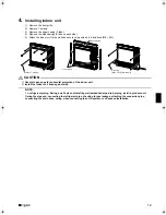
7.

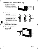
Checking for gas leakage

1) Check for leakage of gas after air purging. 
2) See the sections on air purges and gas leak 

checks in the installation manual for the outdoor 
unit. 

8.

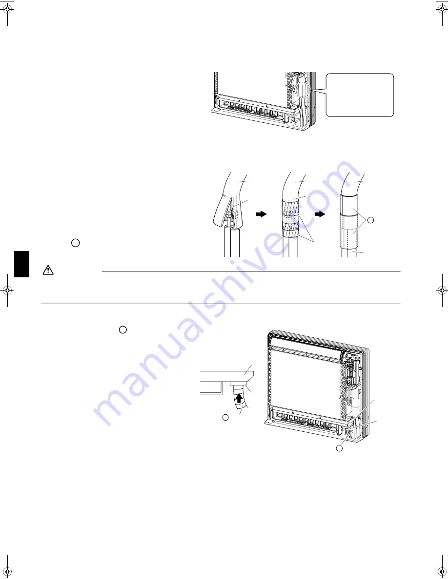
Attaching the connection pipe 

• Attach the pipe after checking for gas leakage, 

described above. 

1) Cut the insulated portion of the on-site piping, 

matching it up with the connecting portion. 

2) Secure the slit on the refrigerant piping side 

with the butt joint on the auxiliary piping using 
the tape, making sure there are no gaps. 

3) Wrap the slit and the butt joint with the included 

 insulation sheet, making sure there are no 

gaps. 

 CAUTION

1)

Insulate the joint of the pipes securely.
Incomplete insulation may lead to water leakage.

2)

Push the pipe inside so it does not place undue force on the front grille.

9.

Connecting the drain hose

Insert the supplied 

 drain hose into the 

socket of the drain pan. 
Fully insert the drain hose until it adheres to 
a seal of the socket.

Check for leakage here.

• Apply soapy water and

check carefully for leaking
gas.

• Wipe soapy water off after

the check is complete.

Refrigerant 
pipe

Refrigerant 
pipe

Refrigerant 
pipe

2)

1)

3)

Auxiliary pipe

Slit

Slit

Tape

Insulation 
sheet

D

D

Drain pan

Drain pan

Seal

Seal

Drain hose

C

Drain hose

C

C

01_EN_3P191292-1E.fm  Page 9  Monday, November 10, 2008  6:44 PM

Summary of Contents for Super Multi NX FVXS25FV1B

Page 1: ...ies Installationsanleitung Split Baureihe R410A Manuel d installation Série split R410A Montagehandleiding R410A Split systeem Manual de instalación Serie Split R410A Manuale d installazione Serie Multiambienti R410A Εγχειρßδιο εγκατÜστασηò διαιροýìενηò σειρÜò R410A Manual de Instalação Série split R410A Рóêоводство по монтажó Серия R410A с раздельной óстановêой Montaj kýlavuzlarý R410A Split seri...

Page 2: ...Japan DAIKIN INDUSTRIES LTD Low Voltage 2006 95 EC Electromagnetic Compatibility 2004 108 EC 3SB64418 7A Shinri Sada Manager Quality Control Department 1st of Nov 2008 DAIKIN TCF 015 K1 07 2007 FVXS25FV1B FVXS35FV1B FVXS50FV1B KEMA Quality B V 74736 KRQ EMC97 4957 ...

Page 3: ...sses Incomplete connections or clamping may cause terminal overheating or fire After connecting interconnecting and supply wiring be sure to shape the cables so that they do not put undue force on the electrical covers or panels Install covers over the wires Incomplete cover installation may cause terminal overheating electrical shock or fire If any refrigerant has leaked out during the installati...

Page 4: ... 1 metre away from any television or radio set unit may cause interference with the picture or sound 2 Wireless remote controller 1 Turn on all fluorescent lamps in the room if any and find site where remote controller signals are properly received by the indoor unit within 7m 2 Make the dipswitch settings Set according to the type of unit purchased by the customer The default settings are on the ...

Page 5: ...Wall Installation Concealed Grid Field supply Mounting plate A Molding 64 644 134 700 600 574 26 140 230 250 35 35 210 160 150 Unit mm Titanium Apatite Photocatalytic Air Purifying Filter 2 B Front grille Air filter Front panel 50mm or more from walls 70mm or more 50mm or more from walls Caulk pipe hole gap with putty Wireless remote controller Screws Field supply M3 20L Remote controller holder E...

Page 6: ...nt panel to the original position 3 How to set the different addresses When two indoor units are installed in one room the two wireless remote controllers can be set for different addresses 1 Remove the front grille 2 Live the sensor securing plate and remove the front metal plate cover 3 Remove connectors 5P 6P and 7P 4 Remove the electric box 1 screw 5 Remove the thermistor 6 Remove the side met...

Page 7: ...th For multi connections see the installation manual for the multi outdoor unit 2 Boring a wall hole and installing wall embedded pipe For walls containing metal frame or metal board be sure to use a wall embedded pipe and wall cover in the feed through hole to prevent possible heat electrical shock or fire Be sure to caulk the gaps around the pipes with caulking material to prevent water leakage ...

Page 8: ...reparation Open the front panel remove the 4 screws and dismount the front grille while pulling it forward Follow the procedure below when removing the slit portions For Moldings Remove the pillars Remove the slit portions on the bottom frame using nippers For Side Piping Remove the pillars 1 Remove the 7 screws 2 Remove the upper casing 2 tabs 3 Remove the left and right casings 2 tabs on each si...

Page 9: ... not enter the pipe 3 Fit the flare nut on the pipe 4 Flare the pipe 5 Check that the flaring is properly made WARNING 1 Do not use mineral oil on flared part 2 Prevent mineral oil from getting into the system as this would reduce the lifetime of the units 3 Never use piping which has been used for previous installations Only use parts which are delivered with the unit 4 Do never install a drier t...

Page 10: ...on materials that will withstand this temperature 2 Be sure to insulate both the gas and liquid piping and to provide insulation dimensions as below 3 Use separate thermal insulation pipes for gas and liquid refrigerant pipes Flare nut tightening torque Gas side Liquid side 25 35 class 50 class 25 35 50 class 3 8 inch 1 2 inch 1 4 inch 32 7 39 9N m 333 407kgf cm 49 5 60 3N m 505 615kgf cm 14 2 17 ...

Page 11: ...gaps 3 Wrap the slit and the butt joint with the included insulation sheet making sure there are no gaps CAUTION 1 Insulate the joint of the pipes securely Incomplete insulation may lead to water leakage 2 Push the pipe inside so it does not place undue force on the front grille 9 Connecting the drain hose Insert the supplied drain hose into the socket of the drain pan Fully insert the drain hose ...

Page 12: ...r for the drain pump etc from the terminal block Doing so may cause electric shock or fire 11 When connecting to an HA system 1 Remove the electric box See 3 How to set the different addresses on page 4 2 Cut off the pins using a nipper 3 Wire as shown in the diagram and connect the connection cord to the S21 connector 4 Attach the side metal plate cover and thermistor sensor and return the electr...

Page 13: ... Be sure to install the supplemental plate in accordance with the depth of the inner wall CAUTION 1 The supplemental plate for installing the main unit must be used or there will be a gap between the unit and the wall 3 Refrigerant piping See 1 Refrigerant piping under Indoor Unit Installation 1 670 690 585 595 Unit mm Open size Opening hole Floor Fixing point on the back Supplemental plate Field ...

Page 14: ...for horizontal projection of the indoor unit 2 Install the indoor unit flush against wall NOTE For refrigerant piping Boring a wall hole and installing wall embedded pipe drain piping installing indoor unit flaring the pipe end connecting the refrigerant pipe checking for gas leakage attaching the connection pipe connecting the drain hose wiring when connecting to an HA system see Exposed Installa...

Page 15: ... not to obstruct the flow of cool warm air 2 Place a partition plate between outlet and inlet sections 3 Place a partition plate on the right side 4 Change the upward blow limit switch 5 Use a movable lattice at the air outlet to allow the adjustment of cool warm air flow direction 6 Lattice size should be 70 or more of open rate Right side partition plate Partition plate 50 or more 50 or more Uni...

Page 16: ...e house NOTE For refrigerant piping Boring a wall hole and installing wall embedded pipe drain piping installing indoor unit flaring the pipe end connecting the refrigerant pipe checking for gas leakage attaching the connection pipe connecting the drain hose wiring when connecting to an HA system see Exposed Installation Left bottom piping Right bottom piping 45 60 75 Hole location Right left pipi...

Page 17: ...uver movement are working properly The air conditioner requires a small amount of power in its standby mode If the system is not to be used for some time after installation shut off the circuit breaker to eliminate unnecessary power consumption If the circuit breaker trips to shut off the power to the air conditioner the system will restore the original operation mode when the circuit breaker is o...

Page 18: ... 0812 HT 3P191292 1E M06B131D Two dimensional bar code is a code for manufacturing ...

Reviews: