PIM-00004
△
1
[Operation Manual]
55/61
DAIKIN INDUSTRIES, LTD.
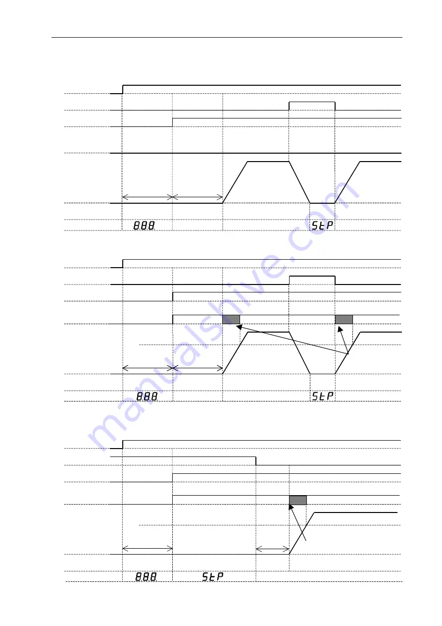
[Attachment: Power-ON External I/O Signal Timing Chart]
1. When parameter [P08] is
“
0
”
1-1 When the pressure switch function is not used
1-2 When the pressure switch function is used
1-3 When the pressure switch function is used (Stop at power-ON)
L: Activated
L: Abnormal
H: Stop command
L: Operation command
H: Normal
Power supply (200V)
Start/stop signal
Alarm/Warning
Pressure switch
(Relay output)
Pressure
Mode
Display
3 sec. max.
0.2 sec. average
Charging
Magnetic pole detection
Actual pressure display
Normal control
Actual pressure display
Actual pressure display
Power supply (200V)
Start/stop signal
Alarm/Warning
Pressure switch
(Relay output)
Pressure
Mode
Display
3 sec. max.
0.2 sec. average
Charging
Magnetic pole detection
Actual pressure display
Normal control
Actual pressure display
Actual pressure display
H: Stop command
L: Operation command
H: Normal
H: Normal pressure condition
The output may be unstable
depending on the relationship
between the pressure switch
setting and delay time.
L: Activated
L: Abnormal
Pressure switch setting
Power supply (200V)
Start/stop signal
Alarm/Warning
Pressure switch
(Relay output)
Pressure
Mode
Display
3 sec. max.
0.2 sec. average
H: Stop command
L: Operation command
H: Normal
H: Normal pressure condition
The output may be unstable depending on the relationship
between the pressure switch setting and delay time.
L: Activated
L: Abnormal
Pressure switch setting
Charging
Magnetic pole
detection
Normal control
Actual pressure display
Standby for operation
* Magnetic pole detection will be executed at the first motor startup after power-ON.


