Si-93
Supplementary Explanation
Supplementary Explanation
53
1. Supplementary Explanation
1.1
Field Setting, Service Mode Operation
1.1.1
Field Setting
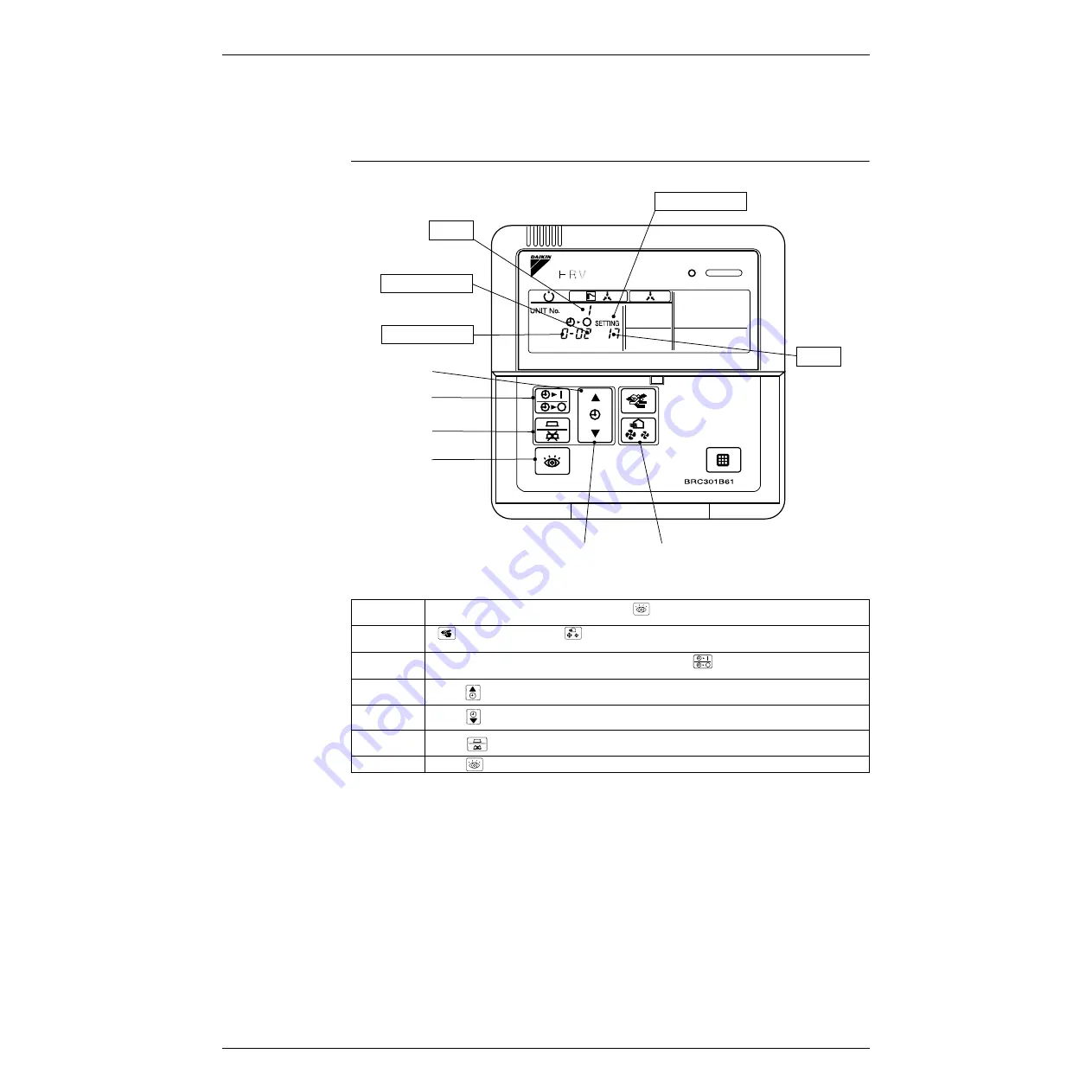
Initial setting (mode
Nos. 17, 27, 18, 28)
4
3
6
1, 7
5
2
Unit No.
Mode No.
Setting position No.
Field setting mode
Setting switch No.
(HL039)
Step 1
With equipment in normal mode, press the
button for more than 4 seconds to enter field
setting mode.
Step 2
Mode No.: UP
↔
Mode No.: DOWN
Use [MODE] and [AIR VOLUME] to select desired mode No.
Step 3
To setting heat reclaim ventilation units by group, press
button and select desired unit
No.
Step 4
Press
button to select desired setting switch No.
Step 5
Press
button to select desired setting position No.
Step 6
Press
button to enter settings.
Step 7
Press
button to return to normal mode.
Summary of Contents for VAM 500EJ
Page 5: ...Si 93 iv Table of Contents...
Page 7: ...Introduction Si 93 vi 1 1 1 Cautions in Repair Warning...
Page 8: ...Si 93 Introduction vii...
Page 11: ...Si 93 2 General Constructions...
Page 15: ...Si 93 6 Operation...
Page 21: ...Si 93 12 Maintenance...
Page 27: ...Si 93 18 Control Functions...
Page 35: ...Si 93 26 Circuit Operations...
Page 39: ...Si 93 30 Troubleshooting...
Page 59: ...Troubleshooting Si 93 50 Troubleshooting...
Page 61: ...Si 93 52 Supplementary Explanation...
Page 72: ...Si 93 Appendix 63 Part 8 Appendix 1 Appendix 65 1 1 Wiring Diagram 65...
Page 73: ...Si 93 64 Appendix...
Page 74: ...Si 93 Appendix Appendix 65 1 Appendix 1 1 Wiring Diagram VAM500EJVE VAM800EJVE VAM1000EJVE...
Page 75: ...Appendix Si 93 66 Appendix VAM2000EJVE...
Page 79: ...Si 93 iv Index...


