12 Electrical installation
Installation and operation manual
17
VAM350~2000J8VEB
Heat reclaim ventilation unit
4P664011-1 – 2021.08
a
b
f
k
d
+e
m
l
i
j
r n h
o
o
m
X35A
X24A
c
i
o
r
n
h
l
q
q
q
c
a
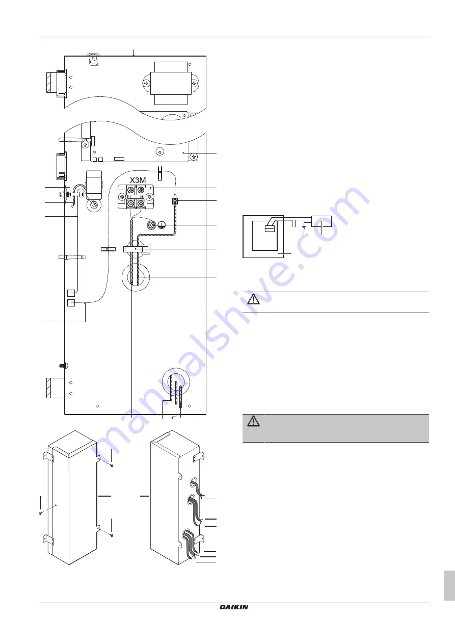
Switch box
b
PCB
c
Switch box cover
d
Securing screw and washer
e
Grounding terminal
f
Terminal board
g
Transmission wiring terminal board (P1, P2, F1, F2)
h
Transmission wiring (to optional controller)
Ii
Power supply cable
j
Wires for connection of additional external damper
(supplied accessory)
k
Insulated splices-closed barrel connector (0.75 mm²)
(field supply)
l
Double or reinforced insulated flexible cable (0.75 mm²)
to external damper (field supply)
m
Tie wrap (field supply)
n
BRP4A50A (optional accessory)
o
KRP2A51 (optional accessory)
p
CO₂ sensor (optional accessory)
q
Tapping screw
r
Wires for fresh-up operation
12.4
Electrical connections for
additional field supplied damper
An external damper prevents the intake of outdoor air when the VAM
is switched off.
The VAM main PCB provides a contact for an external damper.
PCB
X24A
a
b
c
d
a
VAM
b
External damper
c
External damper earthing
d
Power source
CAUTION
Follow the instructions below carefully.
Required electrical connections
Connect one end of the accessory wire to the X24A connector on
the PCB and the other end to the wire leading to the external
damper via an insulated splices-closed barrel connector (0.75 mm²).
The electrical circuit requires a current protection of 3 A and a
maximum voltage of 250 V.
X24A will close the contact when the VAM fan starts operating and it
will open the contact when the fan is stopped.
12.5
To connect the electrical wiring
WARNING
The VAM and the EKVDX indoor unit MUST share the
same electrical safety devices and power supply.
1
Power supply cable
: Route the cable through the frame and
connect the wires to the terminal block (L, N, earth).
2
Secure the power supply with the power supply clamp, as
shown in "Opening the switch box" in the installer and user
reference guide.
3
Transmission cable(s)
: Route the cable(s) through the frame,
connect the wires to the terminal block (P1, P2).


