


EDMMT712101
Product Introduction
VAM-HVE/HVLT Series
9
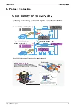
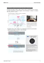
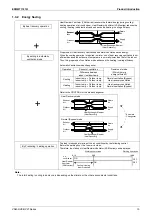
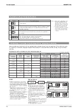
The CO
2
sensor controls airflow rate so that it best matches the changes of CO
2
level in the room.
This prevents energy losses from over-ventilation while maintaining indoor air quality with optional
CO
2
sensor.
Airflow rate up
Many people increase CO
2
level:
Airflow rate down
Fewer people decrease CO
2
level:
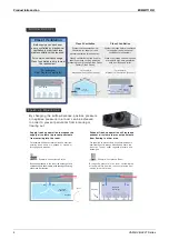
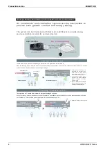
Example of CO
2
sensor operation in an office room:
Heat Reclaim Ventilator
Air conditioner
Air Treatment Equipment
Morning
meetings
Lunch
Time
Sales
personnel leave
office
Sales
personnel
return
Overtime
work
9
10
11
12
13
14
15
16
17
18
19
20
21 Hours
Airflow rate for ventilation
Energy wastage for ventilation is reduced.
Air conditioning load for ventilation is reduced.
CO
2
level
Reference
value
CO
2
level
Airflow rate for ventilation
7- stage control with different airflow levels
indicates energy savings!
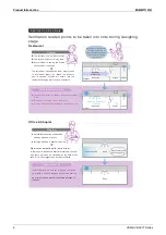
Airflow rate up
Airflow rate up
Airflow rate down
Airflow rate down
If airflow rate
were constant
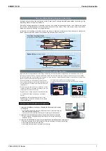
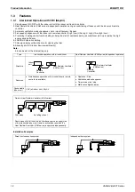
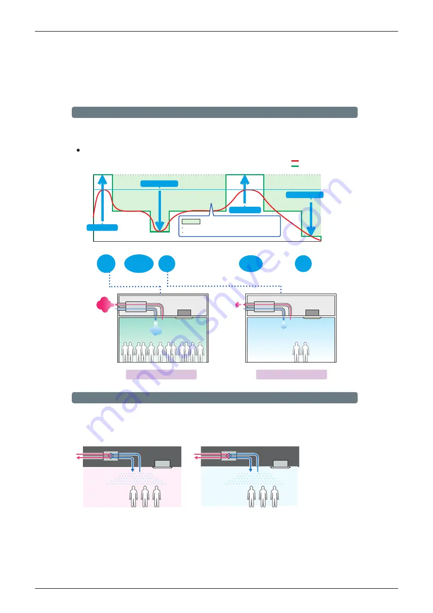
Automatic Ventilation Mode Swithching (Bypass control) with Humidity sensor
The ventilation unit detects room temperature and outside air temperature, then automatically switches to suitable ventilation mode to provide
higher energy-saving. By installing humidity sensor (optional item), the mode will be switched automatically based on the amoun t of heat
(energy) and discomfort index to further improve energy saving and comfort. *1
Suitable ventilation mode depending on condition will be switched automatically
Free cooling after comparing temperature
Free cooling
Air Supply
Exhaust
Energy saving
Operation
Indoor
temperature is
higher
Outdoor temperatur
e is
lower than indoor
Air Supply
Exhaust
Energy saving
Operation
Indoor
temperature is
lower
Outdoor temperatur
e is
lower than indoor
*1 “Energy saving ventilation
mode” or “Comfortable
ventilation mode” can be
selected by local setting.
A i r f l o w r a t e c o n t r o l w i t h CO
2
s e n s o r
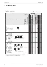
Summary of Contents for VAM Series
Page 2: ......
Page 4: ...EDMMT712101 2 Table of Contents 17 6 Precautions for Design and Installation 181 ...
Page 56: ...Control System EDMMT712101 54 VAM HVE HVLT Series C 3P343420 1E ...
Page 138: ...Installation Manual EDMMT712101 136 VAM HVE HVLT Series 3P607378 3C ...
Page 139: ...EDMMT712101 Installation Manual VAM HVE HVLT Series 137 3P607378 3C ...
Page 141: ...EDMMT712101 Installation Manual VAM HVE HVLT Series 139 C EM20A032 ...
Page 142: ...Installation Manual EDMMT712101 140 VAM HVE HVLT Series C EM20A032 ...
Page 143: ...EDMMT712101 Installation Manual VAM HVE HVLT Series 141 C EM20A032 ...
Page 147: ...EDMMT712101 Details of Optional Accessories VAM HVE HVLT Series 145 3P607378 3C ...
Page 148: ...Details of Optional Accessories EDMMT712101 146 VAM HVE HVLT Series 3P607378 3C ...
Page 149: ...EDMMT712101 Details of Optional Accessories VAM HVE HVLT Series 147 3P607378 3C ...
Page 150: ...Details of Optional Accessories EDMMT712101 148 VAM HVE HVLT Series 3P607378 3C ...
Page 151: ...EDMMT712101 Details of Optional Accessories VAM HVE HVLT Series 149 3P607378 3C ...
Page 152: ...Details of Optional Accessories EDMMT712101 150 VAM HVE HVLT Series 3P607378 3C ...
Page 155: ...EDMMT712101 Details of Optional Accessories VAM HVE HVLT Series 153 4P457318 1D ...
Page 156: ...Details of Optional Accessories EDMMT712101 154 VAM HVE HVLT Series 4P457318 1D ...
Page 157: ...EDMMT712101 Details of Optional Accessories VAM HVE HVLT Series 155 4P457318 1D ...
Page 158: ...Details of Optional Accessories EDMMT712101 156 VAM HVE HVLT Series 4P457318 1D ...
Page 159: ...EDMMT712101 Details of Optional Accessories VAM HVE HVLT Series 157 4P457318 1D ...
Page 184: ......
Page 185: ......
Page 186: ......
Page 187: ......


