Installation Manual
EDMMT712101
126
VAM-HVE/HVLT Series
3P645058-1
4
English
B
E
FOR
E
INSTALLATION
1
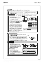
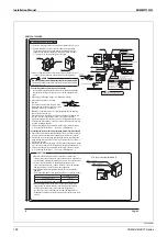
Do not dispose of any parts necessary for installation until the installation is completed.
After bringing in the unit, protect it with packing materials to prevent damage and scratches until installation work is commenced.
S
E
L
E
CTING
INSTALLATION
SIT
E
2
If the temperature and humidity inside the ceiling exceed 30°C or RH80%, apply additional insulation materials
to the main unit. Refer to engineering data for operating areas.
Use glass wool or polyethylene foam as insulation not thicker than 10 mm and fits inside the ceiling opening.
PR
E
PARATIONS
B
E
FOR
E
INSTALLATION
3
(1)
Decide on the transportation route.
(2)
Leave the unit inside its packaging while moving until reaching the installation
site. Where unpacking is unavoidable, protect the unit with protective plates etc. to
avoid damage or scratches to the unit.
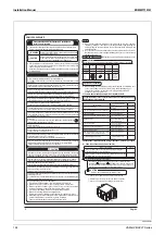
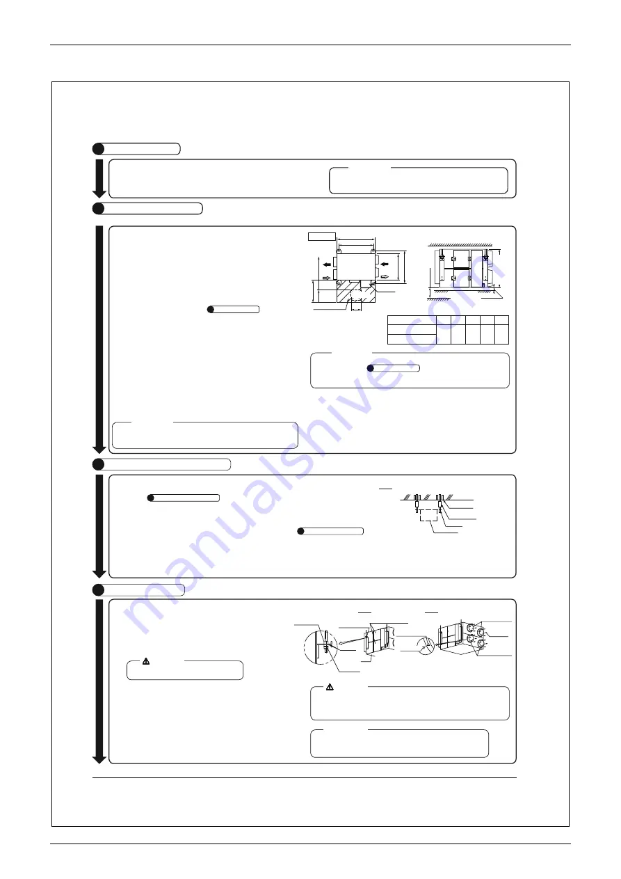
(1) Install the unit temporarily.
y
Attach the lifting lug to the suspension bolt. Be sure to fix it
securely by using nuts (M10, M12) and washers (M10 with
external dia. 30 to 34 mm, M12 with external dia. 32 to 37 mm)
(locally procured) from the upper and lower sides of the lifting
lug. (Refer to Fig. 2)
y
Install the unit after checking the indoor (SA/RA) and outdoor
(EA/OA) sides on the duct layout against the nameplate.
(2) Adjust the height of the unit.
(3) Use a level to make sure that the unit is level.
(4) Tighten the upper nut to fix the main unit in place.
(5)
Attach the duct connector
1
(accessory) with the screw
2
(accessory) to the indoor and outdoor sides (2 locations each).
When attaching, make sure the alignment marking on the main unit
matches up with the triangle
V
on the duct connector. (Refer to Fig. 3)
(6)
Remove the maintenance cover, and remove the tape from the air filter
and heat exchange element.
(7) Attach the maintenance cover.
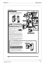
(1)
Confirm the positional relationship between the main unit. Be sure to provide maintenance space for
maintenance and inspection of the air filters, heat exchange element, and blower.
(Refer
to
SELECTING INSTALLATION SITE
2
.
)
Fig. 1
Note) All the above parts are locally procured.
Main unit
Suspension bolt
Long nut or turnbuckle
Foundation bolt
Ceiling slab
(2)
Make sure the range of the unit’s external static pressure is not exceeded. (See the fan characteristics and
engineering data for the range of the external static pressure setting.)
(3)
Open the installation hole in case of pre-set ceilings. Route the power supply wiring, remote controller wiring,
and transmission wiring up to the wiring opening on the main unit. (Refer to
ELECTRICAL WIRING WORK
6
.)
After cutting the ceiling hole, make sure the ceiling is level. It might be necessary to reinforce the ceiling frame
to prevent the ceiling from shaking. Consult an architect or interior designer for details.
(4)
Install the suspension bolts. (Use M10 to M12 suspension bolts.) Use hole-in anchors for existing ceilings,
embedded inserts, or embedded foundation bolts for new ceilings to ensure that the ceiling can withstand the
unit’s weight. Also, adjust the length to the ceiling surface in advance. (Refer to Fig. 1)
Model Names
A
B
C
D
E
VAM1500HVE
1110 1012 1034 1115 785
VAM2000HVE
Return air from
room (RA)
(Suspension bolt pitch)
450
Service space
Inspection hole
Electrical component box
(Suspension bolt pitch)
600 or more
150~250
Fresh air from
outdoors (OA)
Supply air to
room (SA)
Exhaust air to
outdoors (EA)
B
A
C
D
Required space
N=50 or more
(product height)
E
1800 or more
Ceiling surface
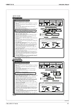
(1) Select an installation site where the following conditions are fulfilled and
that meets with your customer’s approval.
y
Location with sufficient strength and stability (beams, ceiling, and
other locations capable of fully supporting the weight of the unit).
Insufficient strength may result in the unit falling over and causing injury.
It may also cause vibration and unusual noise.
y
Where nothing blocks air passage.
y
Where the unit is not in direct contact with the ceiling or wall.
If the unit is in contact with the ceiling or wall, it can cause vibration.
y
Where sufficient service space and space for duct connection can be secured.
For duct connection, refer to the
DUCT CONNECTION
5
.
y
Where the unit is not in direct contact with the ceiling or wall.
y
Where ceiling materials are present (this unit can be installed only
above the ceiling).
In the absence of ceiling materials, the unit may make noise in quiet
places.
(2) If the unit intakes foggy, misty, or humid air, water droplets will drip from
the air filter or heat exchange element, causing water leakage or failure.
If the room is under negative pressure or if there is a strong outside wind,
the unit may intake outside air even when the unit is not in operation.
In such cases, install an electric shutter, etc., to prevent outside air from
coming in.
(3) Suspension bolts are used for installation. Check whether the installation
location can withstand the weight of the main unit and, if necessary,
reinforce the location with beams, etc., before installing the unit.
t
Hold the lifting lug (4 locations) when moving the unit during or after the unpacking.
t
Do not apply force to other parts (especially to the electrical component box, air intake, air
outlet, and duct connector).
<CAUTION>
Unit [mm]
t
When exhausting into a common duct, it is compulsory to use a fire-protection device pursuant
to the Order for Enforcement of the Building Standards Act. To comply with this legislation, a 2m
steel plate rising duct or a backflow prevention damper must be attached.
<CAUTION>
1. For N dimension, secure the space for downward slope of at least 1/30 necessary for the outdoor duct
to be connected. (Refer to
DUCT CONNECTION
5
.)
2. Service space is necessary for maintenance (cleaning) of the filters and for servicing of the various
parts. Be sure to provide inspection holes and service space.
<CAUTION>
Do not insert any part or component between the
lifting lug and lifting lug washer.
WARNING
Install the unit in a location that can adequately withstand its mass.
Insufficient strength may result in the indoor unit falling over and causing injury.
t
Refer to the “Guidelines for the Seismic Design and Construction of Building Equipment”
(Building Center of Japan) for information on the seismic performance of equipment.
WARNING
Be sure to use the provided screws for the duct connector.
Failure to use the provided screws could cause screws to contact internal parts,
resulting in lower performance.
<CAUTION>
Fig. 3
Fig. 2
(locally procured)
Lifting lug
Main unit
Main unit
alignment
Marking on duct
connector
Duct connector
1
(accessory)
Duct connector
1
(accessory)
Screw
2
(accessory)
Washer
(locally procured)
Double nut
(locally procured)
Maintenance cover
INSTALLATION
M
E
THOD
4
<Be sure to use only the specified parts and accessories for facility construction.>
VAM1500-2000HV
E
Summary of Contents for VAM Series
Page 2: ......
Page 4: ...EDMMT712101 2 Table of Contents 17 6 Precautions for Design and Installation 181 ...
Page 56: ...Control System EDMMT712101 54 VAM HVE HVLT Series C 3P343420 1E ...
Page 138: ...Installation Manual EDMMT712101 136 VAM HVE HVLT Series 3P607378 3C ...
Page 139: ...EDMMT712101 Installation Manual VAM HVE HVLT Series 137 3P607378 3C ...
Page 141: ...EDMMT712101 Installation Manual VAM HVE HVLT Series 139 C EM20A032 ...
Page 142: ...Installation Manual EDMMT712101 140 VAM HVE HVLT Series C EM20A032 ...
Page 143: ...EDMMT712101 Installation Manual VAM HVE HVLT Series 141 C EM20A032 ...
Page 147: ...EDMMT712101 Details of Optional Accessories VAM HVE HVLT Series 145 3P607378 3C ...
Page 148: ...Details of Optional Accessories EDMMT712101 146 VAM HVE HVLT Series 3P607378 3C ...
Page 149: ...EDMMT712101 Details of Optional Accessories VAM HVE HVLT Series 147 3P607378 3C ...
Page 150: ...Details of Optional Accessories EDMMT712101 148 VAM HVE HVLT Series 3P607378 3C ...
Page 151: ...EDMMT712101 Details of Optional Accessories VAM HVE HVLT Series 149 3P607378 3C ...
Page 152: ...Details of Optional Accessories EDMMT712101 150 VAM HVE HVLT Series 3P607378 3C ...
Page 155: ...EDMMT712101 Details of Optional Accessories VAM HVE HVLT Series 153 4P457318 1D ...
Page 156: ...Details of Optional Accessories EDMMT712101 154 VAM HVE HVLT Series 4P457318 1D ...
Page 157: ...EDMMT712101 Details of Optional Accessories VAM HVE HVLT Series 155 4P457318 1D ...
Page 158: ...Details of Optional Accessories EDMMT712101 156 VAM HVE HVLT Series 4P457318 1D ...
Page 159: ...EDMMT712101 Details of Optional Accessories VAM HVE HVLT Series 157 4P457318 1D ...
Page 184: ......
Page 185: ......
Page 186: ......
Page 187: ......


